
Motor vehicle with partition

a technology for motor vehicles and loading compartments, applied in the direction of vehicular safety arrangements, transportation items, pedestrian/occupant safety arrangements, etc., can solve the problems of additional useable space provided at the expense of the driver's compartment, and achieve the effect of ensuring the safety of the necessary compartment, enhancing the strength of the vehicle structure, and extending the loading compartmen

Inactive Publication Date: 2006-04-20
DAIMLER AG
View PDF3 Cites 11 Cited by
  • Summary
  • Abstract
  • Description
  • Claims
  • Application Information

AI Technical Summary

Benefits of technology

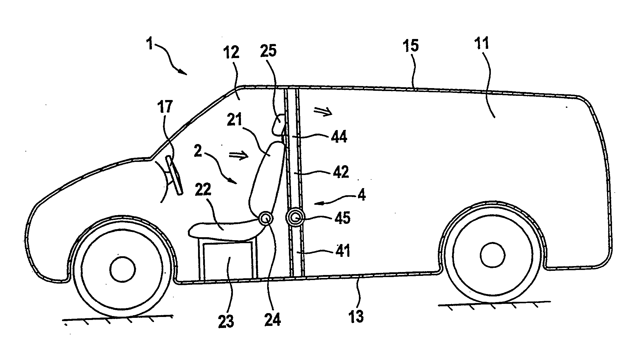
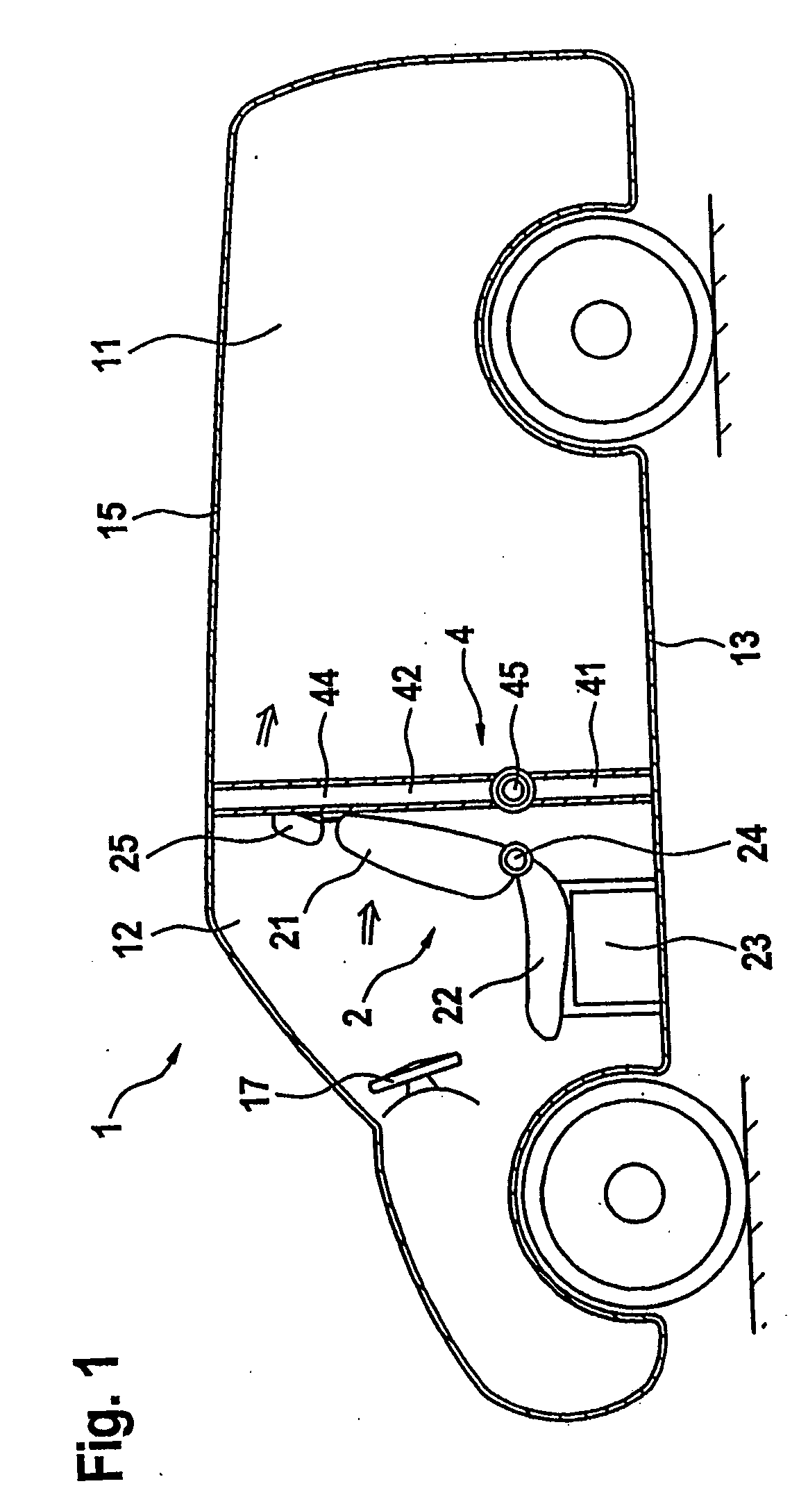
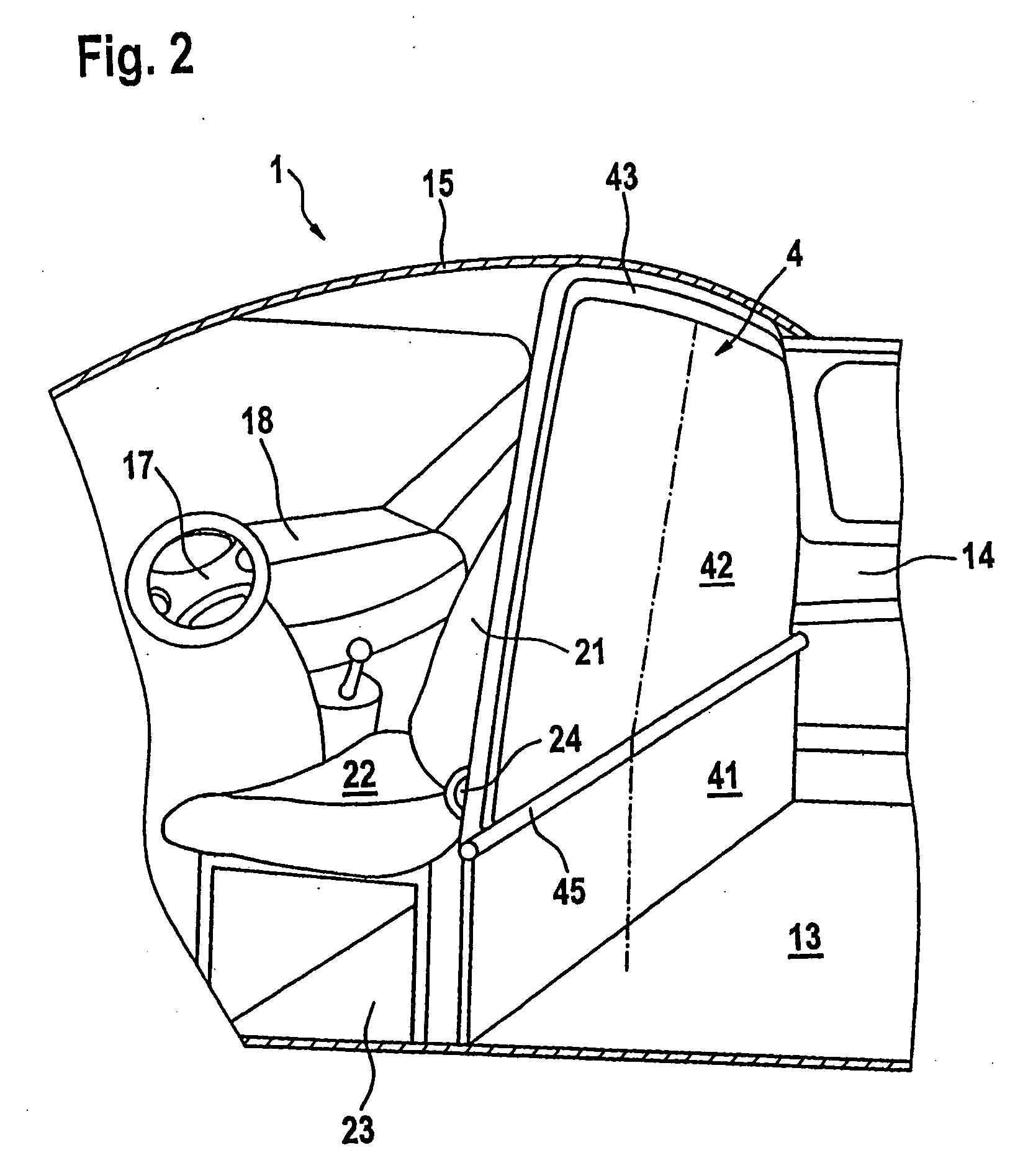
[0006] The partition of the motor vehicle according to the invention has two surfaces which are connected to each other via a hinge running transversely with respect to the vehicle floor. A first surface is arranged in the lower region of the vehicle and is connected fixedly both to the vehicle floor and also, on both sides, to the vehicle wall. As a result, this surface forms a stable termination of the loading compartment and increases the strength of the vehicle structure. The second surface of the partition is arranged in the upper region of the vehicle and can be pivoted by means of the hinge. The second surface is secured fixedly in various pivoting angles via a latching device arranged in the region of the vehicle roof.
[0007] The pivoting of the upper part of the partition therefore enables either the driver's compartment to be enlarged, by the partition being pivoted in the direction of the loading compartment, or it enables the loading compartment to be enlarged by the partition being pivoted in the direction of the driver's compartment. As a result, it is possible for even very large drivers, with a predetermined size of the driver's compartment, to be able to push the vehicle seat back a long way or to be able to incline the backrest rearward a long way in order to take up a comfortable and ergonomic sitting position. For this purpose, the partition is pivoted toward the loading compartment, so that the necessary space is created for the driver.
[0008] In the case of smaller drivers or in the case of very large freight items, the partition can be pivoted forward toward the driver's compartment, so that an enlarged loading compartment is obtained. A stable connection of the upper, second surface of the partition to the vehicle body is produced via the fixed, lower segment of the partition and the hinge. A latching device is provided at the upper end of the second surface and connects the latter fixedly to the vehicle roof. As a result, the necessary safety is ensured even in the event of a crash by items of luggage being securely retained in the loading compartment by the partition during sharp braking maneuvers or a crash.
[0009] In one embodiment, provision is made for the latching device to have two intermeshing racks. The first rack is connected fixedly to the vehicle body, preferably the structure of the vehicle roof. The second rack is connected in an articulated manner to the second surface of the partition. The two racks engage in one another and therefore define a certain set angle of the second surface. The articulated suspension of the second rack makes it possible for a relatively large angular region to be able to be covered while the two racks remain constantly stably connected.
[0010] In particular, provision can be made for the latching device to have a prestressed spring which pressurizes the second rack in the direction of the first rack. As a result, the mechanical connection of the two racks is further improved and the retaining force of the latching device is increased.
[0011] One embodiment makes provision for the setting of the teeth of the two racks to be designed in such a manner that a movement of the second rack forward in the direction of travel is blocked and a movement of the second rack rearward counter to the direction of travel is made possible in the event of it being pressed over the latching. As a result, a simple possibility of adjusting the upper partition section in the direction of the loading compartment is obtained and at the same time a particularly good support of the partition is obtained should items of luggage impact against the partition in the direction of the driver's compartment.

Problems solved by technology

As a result, an additional useable space is provided at the expense of the driver's compartment.

Method used


Image

  • Motor vehicle with partition
  • Motor vehicle with partition
  • Motor vehicle with partition

Examples


Embodiment Construction

[0022]FIG. 1 illustrates a motor vehicle 1 with a loading compartment 11 and a driver's compartment 12. The loading compartment 11 is terminated downward by a motor vehicle floor 13 and upward by a motor vehicle roof 15 and laterally by side walls 14. A vehicle seat 2 is arranged in the driver's compartment 12 which is arranged in front of the loading compartment in the direction of travel, said vehicle seat 2 having a seat cushion 22 and a backrest 21 connected pivotably to the latter via a rotary fitting 24. A height-adjustable head restraint 25 is arranged at the upper end of the back rest 21. The vehicle seat 2 is connected to the motor vehicle floor 13 via a seat box 23 and can be displaced on the seat box 23 in the longitudinal direction of the vehicle, that is to say forward or rearward, via guide rails in order to set a desired sitting position. Furthermore, the backrest 21 can be adjusted in inclination via the rotary fitting 24, so that a driver can set the sitting positio...


PUM


Abstract

A motor vehicle has a loading compartment and a driver's compartment which is separated from the loading compartment via a partition. In order to permit great variability by making good use of the space, the partition is of two-part design, with the two parts being connected to each other via a hinge. The hinge makes it possible for the second part to be able to be pivoted in relation to the fixed, lower part toward the loading compartment or toward the driver's compartment. A latching device secures the partition in various pivoting angles.

Description

[0001] This application claims the priority of German application 10 2004 051 015.6, filed Oct. 20, 2004, the disclosure of which is expressly incorporated by reference herein. BACKGROUND AND SUMMARY OF THE INVENTION [0002] This invention relates to a motor vehicle with a closed loading compartment and a driver's compartment which is separated from the loading compartment via a partition, which has an adjustable vehicle seat, in which the partition includes at least first and second surfaces which are connected pivotably to each other, and in which a hinge runs parallel to a vehicle floor and pivotally connects the surfaces to each other. [0003] German document DE 19751671 A1 discloses a partition for minibuses or trucksters. The partition runs transversely with respect to the longitudinal direction of the vehicle and separates a driver's compartment from a useable space. In order to enlarge the useable space available, this partition is designed in such a manner that it has an uppe...

Claims


Application Information

Patent Timeline
Patent Type & Authority Applications(United States)
IPC IPC(8): B60P7/14
CPCB60R21/026
Inventor ALLGAYER, HOLGERSCHLEIFE, HOLGER
Owner DAIMLER AG
Learn More