Hydraulic motor

a technology of hydraulic motors and cylinders, applied in the direction of mechanical equipment, engines with rotating cylinders, liquid fuel engines, etc., can solve the problems of increasing manufacturing costs and achieve the effect of accurate rotation constraints

Inactive Publication Date: 2001-02-13
SA POCLAIN HYDRAULICS B P
View PDF6 Cites 10 Cited by
  • Summary
  • Abstract
  • Description
  • Claims
  • Application Information

AI Technical Summary

Benefits of technology

The present invention seeks to provide a simplified system making it possible to ensure accurate constraint in rotation of the distributor and of the distribution cover while also facilitating assembly of the motor, i.e., in particular, simplifying assembly of the subassembly constituted by the distributor and the distribution cover relative to the cylinder block, while holding the distributor axially in the distribution cover and simultaneously making axial movement of the distributor possible as is required in operation, but doing so to an extent that is only just sufficient, so as to guarantee that the sealing gaskets stay in their housings without any risk of being damaged.
It will be understood that by very simple machining consisting in providing the first and second housing respectively in the axial portion of the distribution cover and in the axial portion of the distributor and by using a single pin, the distributor is prevented form rotating relative to the distribution cover, In addition, the pin also provides axial locking since when maximum axial clearance is obtained between the distributor and the distribution cover, the pin co-operates in abutment with the first and second wall elements to prevent the distributor from moving relative to the distribution cover in the axial direction tending to bring the distributor closer to the cylinder block, thereby greatly simplifying assembly.

Problems solved by technology

Although those various solutions do indeed make it possible to ensure positioning in rotation, at least those which use the radial flange suffer from the major drawback of requiring special machining of the distributor and of thereby increasing manufacturing costs.

Method used


Image

  • Hydraulic motor
  • Hydraulic motor
  • Hydraulic motor

Examples


Embodiment Construction

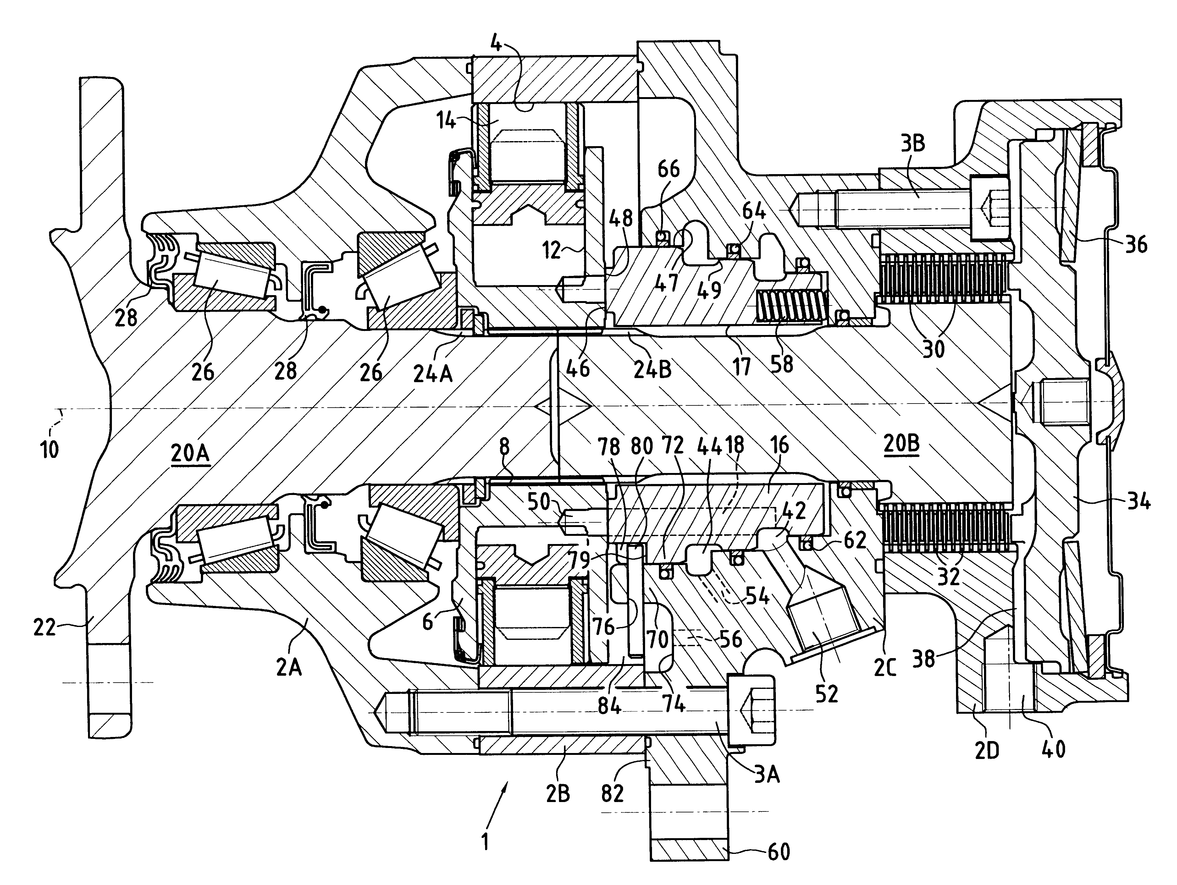
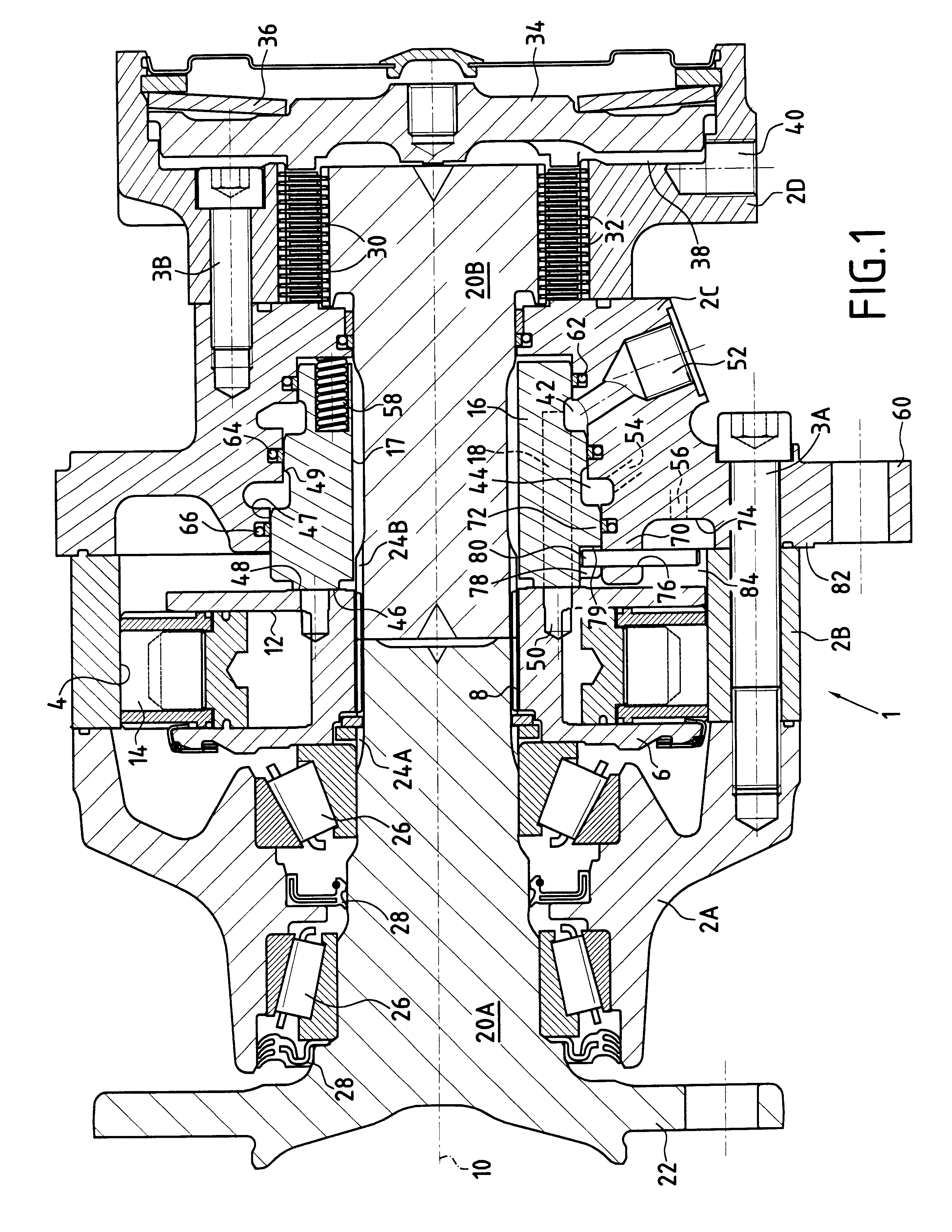
The hydraulic motor 1 shown in FIG. 1 comprises:

a fixed case comprising four portions 2A, 2B, 2C, and 2D, the portions 2A, 2B, and 2C being assembled together by screws 3A, while the portions 2C and 2D are assembled together by screws 3B;

an undulating reaction cam 4 formed on the inside periphery of portion 2B of the case;

a cylinder block 6 having a central bore 8 and mounted to rotate relative to the undulating reaction cam 4 about an axis of rotation 10, the cylinder block having a plurality of radial cylinders 12 suitable for being fed with fluid under pressure, and having pistons 14 slidably mounted therein;

an internal fluid distributor 16 secured to the case against rotation about the axis 10 (i.e., like the 10), and including distribution ducts 18 suitable for communicating with the cylinders 12;

a shaft in tow portions, a first portion 20A being disposed inside case portions 2A and 2B and having one end situated outside the case (projecting beyond case portions 2A) where it ha...


PUM


Abstract

A hydraulic motor comprises a fixed case, a reaction member secured to the case, a cylinder block mounted to rotate relative thereto about an axis of rotation, and an internal fluid distributor prevented from rotating about the axis relative to the case. The case has a "distribution cover" portion situated around the have respective first and second housings are formed to received a pin which prevents relative rotation while allowing the distribution cover in an axial direction, thereby preventing the distributor from separating from the cover while the motor is being assembled.

Description

The present invention relates to a hydraulic motor comprising:a fixed case;a reaction member secured to the case;a cylinder block mounted to rotate relative to said reaction member about an axis of rotation and comprising a plurality of cylinder and piston assemblies disposed radially relative to the axis of rotation and capable of being fed with fluid under pressure, the cylinder block having a communication face perpendicular to the axis of rotation; andan internal fluid distributor secured to the case to prevent rotation about the axis of rotation and having a distribution face perpendicular to the axis of rotation and suitable for being pressed against the communication face of the cylinder block, and a first connection face, said distributor including distribution ducts which extend between the first connection face and the distribution face;the case having a "distribution cover" portion situated around the distributor and presenting a second connection face situated facing the...

Claims


Application Information

Patent Timeline
Patent Type & Authority Patents(United States)
IPC IPC(8): F04B53/22F04B53/00F03C1/38F03C1/00
CPCF03C1/0444F04B53/22
Inventor ALLART, BERNARDBIGO, LOUISPEROT, MARC
Owner SA POCLAIN HYDRAULICS B P
Why Eureka
Try Eureka