Monorail Vehicle Apparatus with Gravity-Controlled Roll Attitude and Loading

a vehicle and gravity control technology, applied in monorails, constructions, roads, etc., can solve the problems of not teaching control forces, unable to support accurate trolley localization on non-featured rails, and more challenging constraining of rotation about longitudinal direction or about rails. to achieve the effect of accurate constraint of roll attitude and lateral translation

Inactive Publication Date: 2014-06-26
SOLARCITY
View PDF1 Cites 16 Cited by
  • Summary
  • Abstract
  • Description
  • Claims
  • Application Information

AI Technical Summary

Benefits of technology

[0016]In view of the above shortcomings of the prior art, it is an object of the present invention to provide for monorail vehicle apparatus and methods that enable deployment of low-cost, low-quality, off-the-shelf (stock) rails including those with a rectangular or square cross-sections and substantial profile variation while retaining the advantages of constant contact force on the bogie's roll-control wheels as well as accurate constraint of roll attitude and lateral translation.

Problems solved by technology

The design and manner of engagement between carriages or bogies of monorail vehicles and the non-featured rail or monorail presents a number of challenges specific to these vehicles.
Roll, the rotation about the longitudinal direction or about the rail is more challenging to constrain.
However, Kaufman's monorail trolley does not teach to control forces on lateral wheels to control the roll axis and roll attitude and it does not support accurate trolley localization on a non-featured rail.
Furthermore, this design is not appropriate for rail that has have long unsupported spans that place restrictions on minimum torsional stiffness, minimum lateral bending stiffness, minimum vertical bending stiffness and maximum material stress.
In fact, a transportation system as taught by Sullivan incurs high torsional forces that would not be appropriate in situations deploying rails having substantially varying profiles (e.g., low-grade stock rails whose cross-sections exhibit substantial profile variation) and rail that contemporaneously have long unsupported spans that place restrictions on minimum torsional stiffness, minimum bending stiffness and maximum material stress.
Again, although Timan's solutions use uniform cross-section rails and address the roll of the monorail bogie, they are not appropriate for rails whose cross-sections exhibit substantial profile variation and require a vehicle with a multitude of mechanisms for controlling the monorail bogie with respect to the rail.
Unfortunately, deployment of large opposing springs to clamp the rail is undesirable in many applications.
Such mechanisms involve many parts, are unreliable and contribute to vehicle cost and mass.
Further, in the case in which the apparatus must use an unsupported guide rail that is as small and inexpensive as possible and the vehicle of the apparatus must be accurately located, the prior art does not produce a satisfactory solution.
Further, as the rail is unsupported over long lengths, such a rail would be additionally constrained by limitations on minimum torsional stiffness, minimum lateral bending stiffness, minimum vertical bending stiffness and maximum material stress.
These additional requirements mean that the featured cross-sections as taught in the first general approach in the prior art are not viable for unsupported spans.
Thus, the prior art struggles to deliver accurate location of a vehicle under these constraints.
A high preload creates high rolling resistance, increases wheel wear, and increases the amount of deflection seen by the wheel, making this solution undesirable.
In other words, a suspension system compatible with low-cost rail using opposing springs would either inaccurately locate to the rail or require excessive preloads to ensure contact during vehicle travel.
Thus, prior art approaches exhibit many limitations that render them inappropriate for controlling roll in monorail vehicles that are deployed on low-cost, low-quality, non-featured stock rails with substantially varying profiles and requiring long unsupported spans.

Method used


Image

  • Monorail Vehicle Apparatus with Gravity-Controlled Roll Attitude and Loading
  • Monorail Vehicle Apparatus with Gravity-Controlled Roll Attitude and Loading
  • Monorail Vehicle Apparatus with Gravity-Controlled Roll Attitude and Loading

Examples


Embodiment Construction

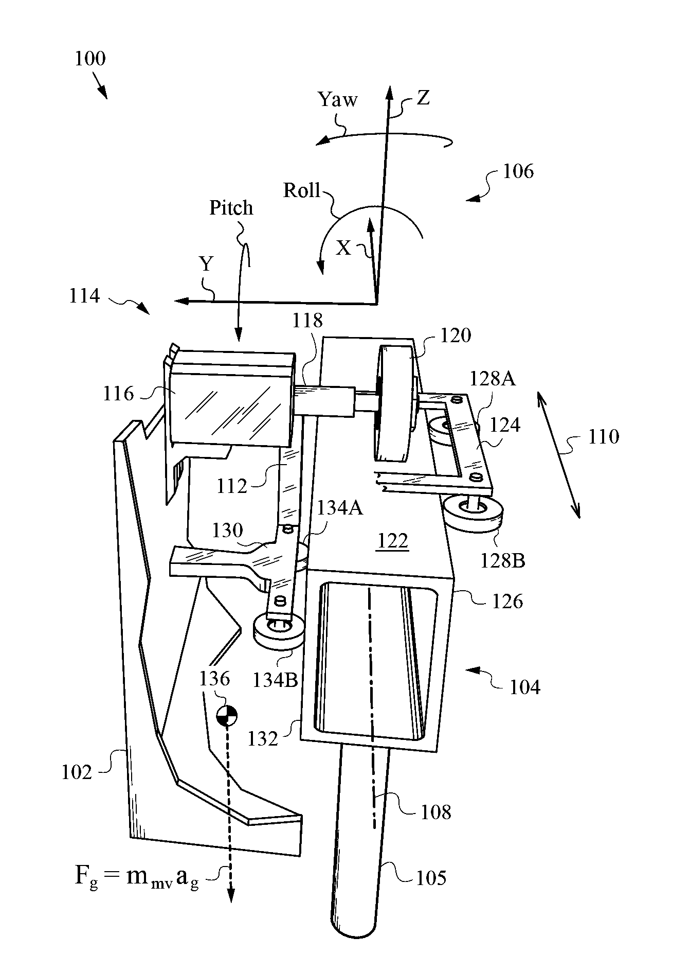
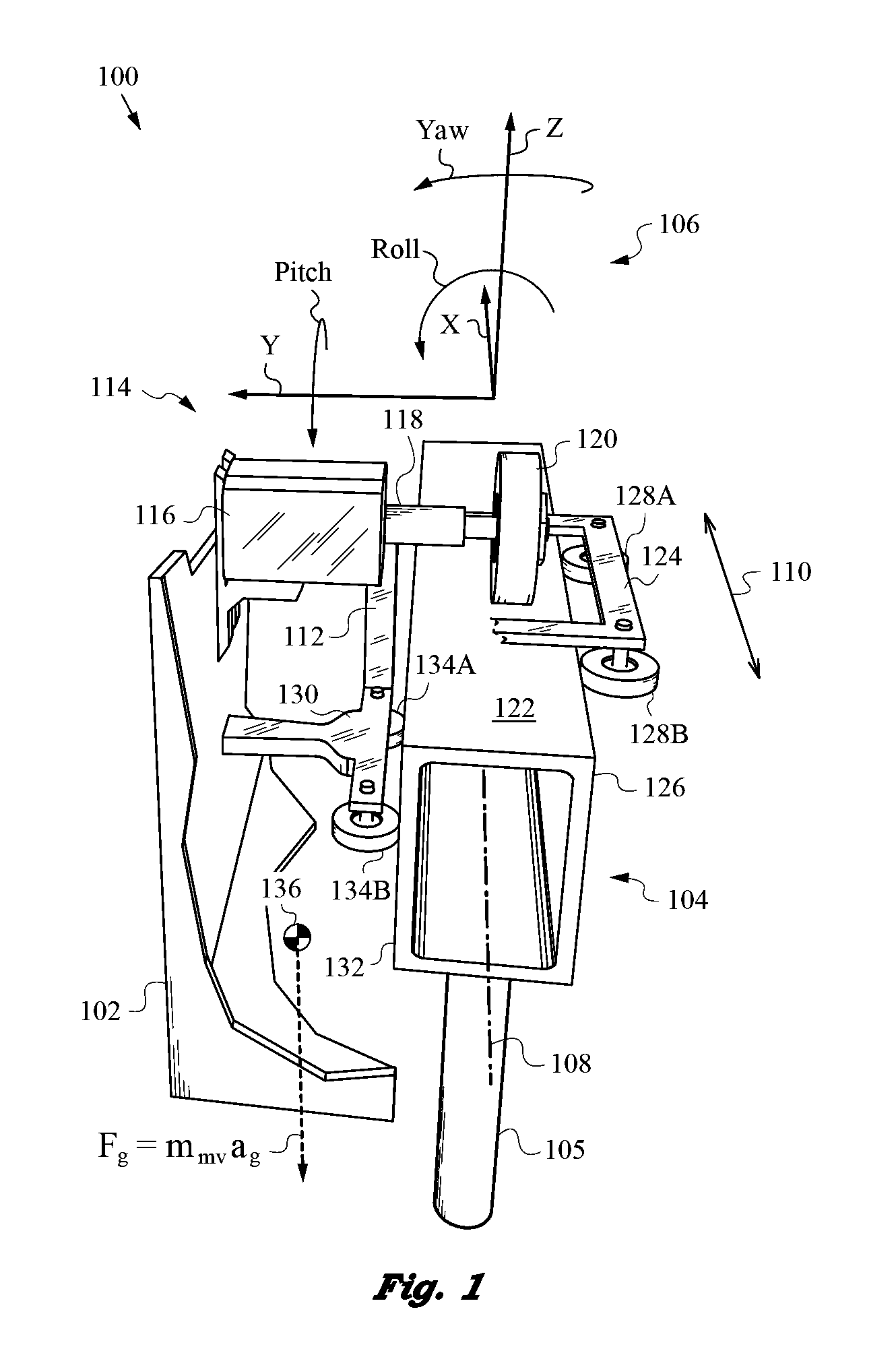
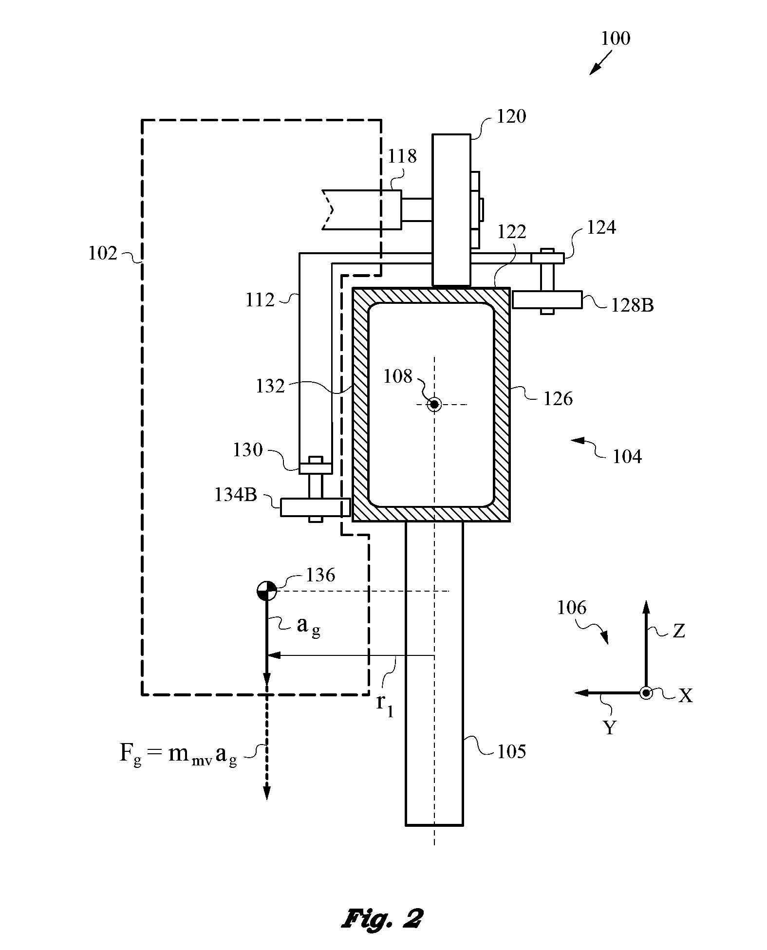
[0048]The figures and the following description relate to preferred embodiments of the present invention by way of illustration only. It should be noted that alternative embodiments of the structures and methods disclosed herein will be readily recognized as viable options that can be employed without departing from the principles of the claimed invention.

[0049]Reference will now be made to several embodiments of the present invention, examples of which are illustrated in the accompanying figures. Similar or like reference numbers are used to indicate similar or like functionality wherever practicable. The figures depict embodiments of the present invention for purposes of illustration only. One skilled in the art will readily recognize from the following description that alternative embodiments of the structures and methods illustrated herein may be employed without departing from the principles of the invention described herein.

[0050]The present invention will be best understood b...


PUM


Abstract

Monorail vehicle that travels on a non-featured rail with substantial profile variation and controls roll attitude, lateral location, and loading through judicious placement of the vehicle's center of gravity without using springs or suspensions. The vehicle has a bogie for engaging the non-featured rail so the center of gravity has a lateral offset r1 from the rail centerline to produce a roll moment Nr determined by vehicle's mass and value of r1. The center of gravity also has a vertical offset r2. The bogie uses first and second assemblies for engaging the rail to produce a pair of surface normal reaction forces to thus control roll attitude and loading by the placement of the center of gravity, thereby enabling accurate alignment of the monorail vehicle.

Description

FIELD OF THE INVENTION[0001]This application is related to monorail vehicle apparatus and methods for constraining the roll attitude, lateral location and loading of such monorail vehicle, and more precisely still, to constraining the roll attitude, lateral location and loading through appropriate placement of the center of gravity of the monorail vehicle at a certain offset to the non-featured rail, as well as appropriate placement of assemblies that interface with the non-featured rail.BACKGROUND ART[0002]Many types of cars, carts, vehicles and trolleys are supported on bogies or trucks that are designed for engagement with and travel on non-featured rails. A subset of such vehicles constrained to travel on rails includes those engineered for travel on a single rail. The latter are commonly referred to as monorail vehicles. The design and manner of engagement between carriages or bogies of monorail vehicles and the non-featured rail or monorail presents a number of challenges spec...

Claims


Application Information

Patent Timeline
Patent Type & Authority Applications(United States)
IPC IPC(8): B61B13/04
CPCB61B13/04
Inventor CAMP, JOHN S.SUMERS, BENJAMIN D.FEELEY, RYAN P.MORI, KEVIN T.FUKUBA, DANIEL L.BOKHARI, WASIQ
Owner SOLARCITY
Why Eureka
Try Eureka