AI technical title is built by Patsnap AI team. It summarizes the technical point description of the patent document.
a technology of low height and imaging system, which is applied in the field of low height imaging system and associated methods, can solve the problems of insufficient freedom to control the variety of optical and mechanical aberrations, and affecting the quality of low-level imaging, etc., and achieves the ideal design or alignment of the different components. , it is difficult to adjust any of the components once assembled, and the difficulty of achieving
Active Publication Date: 2008-11-18
OMNIVISION TECH INC
View PDF75 Cites 13 Cited by
Summary
Abstract
Description
Claims
Application Information
AI Technical Summary
This helps you quickly interpret patents by identifying the three key elements:
Problems solved by technology
Method used
Benefits of technology
Problems solved by technology
While the currently available, compact imaging devices are adequate for low resolution image capture for personal enjoyment, most provide rather low imaging quality or are undesirably long.
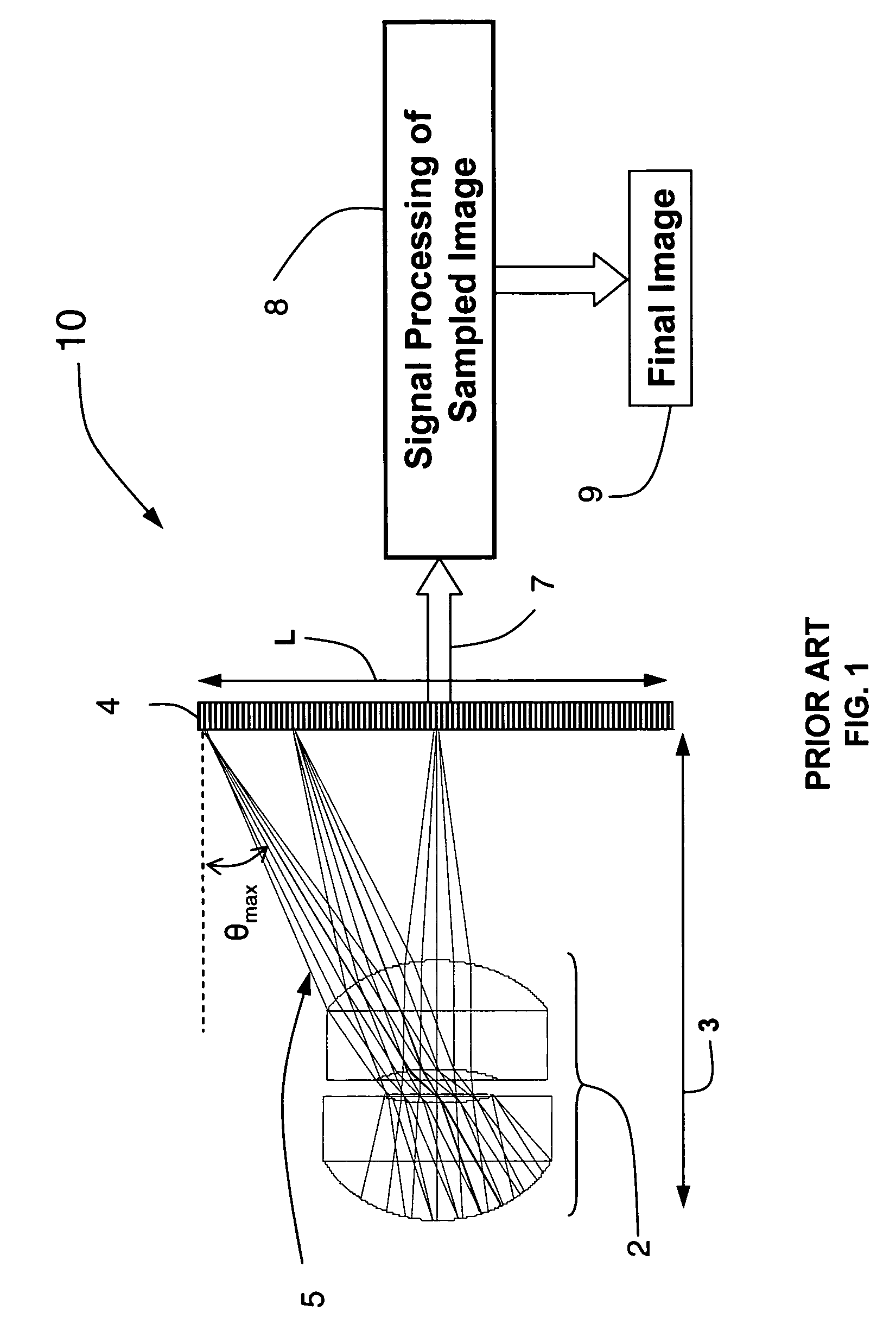
Continuing to refer to FIG. 1, system 10 (like numerous other short imaging systems) does not have sufficient degrees of freedom to control the variety of optical and mechanical aberrations that are possibly manifest in the system.
That is, since there are so few parts forming the system (e.g., just a few lenses and their holders, small detector, etc.) and the components are so small in compact applications such as a miniature camera, it is difficult to achieve an ideal design or alignment of the different components and / or to adjust any of the components once assembled.
As a result, the resulting images do not have high image quality.
This requirement increases the cost of system 10, even though the image quality of the resulting system is relatively poor.
Also, large ray angles may lead to light being captured by the wrong pixel on the detector, thereby causing pixel cross-talk.
Therefore, as images formed with practical CMOS, CCD, and IR detectors are degraded when the incident light rays are far from the normal of the detector, large chief ray angles are undesirable.
As the Z-length of the system is additionally shortened in an effort to further miniaturize the system, these ray angle problems are exacerbated and increasingly lead to reduced image quality.
Method used
Image
Click on the blue label to locate the original text in one second.
Reading with bidirectional positioning of images and text.
Examples
Embodiment Construction
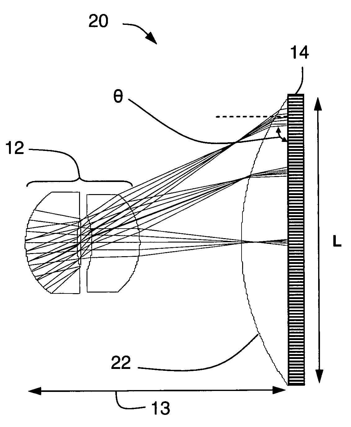
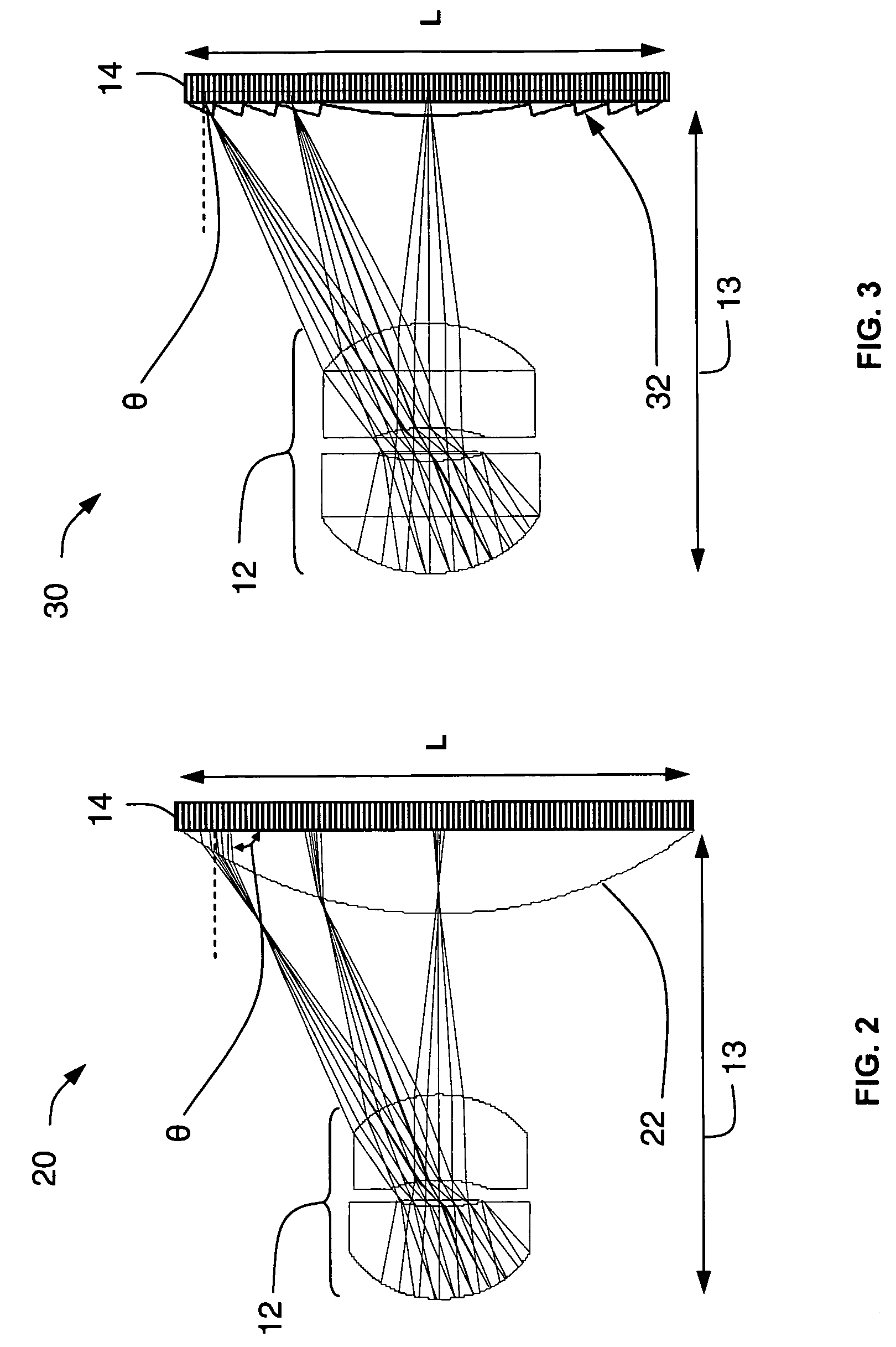
[0063]Optical systems and devices are now described which increase image quality even though they have a short z-length, or equivalently low height, with respect to the size of the detector. “Short” or “low height” is generally defined as a Z-length (from the first surface of the optics to the front of the detector) that is less than twice the effective focal length of the optical system.
[0064]These systems and devices may provide other advantages, for example they may provide: relaxed tolerances (to reduce costs) of the optics, mechanics, and digital detector while still achieving high image quality; for use of modified off-the-shelf short volume optics for high quality imaging; for use of customized short volume optics for high quality imaging; for use of customized short volume optics with reflections for high quality imaging; for use of groups of short volume optics to form high quality images; for use design of specialized exit pupils for specialized imaging systems such that d...
PUM
Abstract
Low height imaging systems may include one or more optical channels and a detector array. Each of the optical channels may be associated with one or more detectors of the array, have one or more optical components and a restrictive ray corrector, and be configured to direct steeper incident angle field rays onto the detectors. Alternatively, each of the optical channels may be associated with at least one detector, and have an aspheric GRIN lens. Another low height imaging system has an array of detectors and a GRIN lens having a surface with wavefront coding and configured to direct steeper incident angle field rays onto more than one of the detectors. One method forms a lens with wavefront coding. The method includes positioning a lens in a mold; and curing material onto a surface of the lens to form an aspheric surface of the lens with wavefront coding.
Description
CROSS REFERENCE TO RELATED APPLICATIONS[0001]The present application claims priority to U.S. Provisional Applications Ser. No. 60 / 609,578, filed on Sep. 14, 2004, entitled Improved Miniature Camera and Ser. No. 60 / 697,710, filed on Jul. 8, 2005, entitled Ray Correction Apparatus and Method, both of which applications are hereby incorporated by reference in their entireties. The following U.S. patents are also incorporated by reference in their entireties: U.S. Pat. No. 5,748,371, entitled Extended Depth of Field Optical Systems to Cathey et al., U.S. Pat. No. 6,525,302, entitled Wavefront coding phase contrast imaging systems to Dowski, Jr., et al., U.S. Pat. No. 6,783,733, entitled Combined wavefront coding and amplitude contrast imaging systems to Dowski, Jr., U.S. Pat. No. 6,842,297, entitled Wavefront coding optics to Dowski, Jr., U.S. Pat. No. 6,911,638, entitled Wavefront coding zoom lens imaging systems to Dowski, Jr., et al. and U.S. Pat. No. 6,940,649, entitled Wavefront co...
Claims
Application Information
Patent Timeline
Application Date:The date an application was filed.
Publication Date:The date a patent or application was officially published.
First Publication Date:The earliest publication date of a patent with the same application number.
Issue Date:Publication date of the patent grant document.
PCT Entry Date:The Entry date of PCT National Phase.
Estimated Expiry Date:The statutory expiry date of a patent right according to the Patent Law, and it is the longest term of protection that the patent right can achieve without the termination of the patent right due to other reasons(Term extension factor has been taken into account ).
Invalid Date:Actual expiry date is based on effective date or publication date of legal transaction data of invalid patent.

