Snorkel device for flow control

a flow control device and funnel technology, applied in the direction of fluid removal, sealing/packing, borehole/well accessories, etc., can solve the problems of limiting the operation envelope of the flow control device, the number of control line penetrations that can be made at the wellhead, and the number of control lines required

Inactive Publication Date: 2008-11-25
SCHLUMBERGER TECH CORP
View PDF48 Cites 19 Cited by
  • Summary
  • Abstract
  • Description
  • Claims
  • Application Information

AI Technical Summary

Problems solved by technology

In running intelligent completions into subterranean wells, there are often limitations on the number of control line penetrations that can be made at the wellhead, the tubing hanger, or, in some cases, the production packer.
When multiple valves of that kind are run in the hole, the number of control lines required becomes a problem.
Since downhole conditions may change over time, selection of the spring or nitrogen charge is critical and may limit the operational envelope of the flow control device.
Various multiplexing schemes have been employed, but those typically require some complex scheme of valves to allow pressures at different levels to address one valve or another.
A common return line has been proposed for simple, two position-type valves (i.e., open / close valves), but operation can be tricky as one must carefully assess the state of each valve to determine the proper pressure sequence to apply to the various control lines at surface.

Method used


Image

  • Snorkel device for flow control
  • Snorkel device for flow control
  • Snorkel device for flow control

Examples


Embodiment Construction

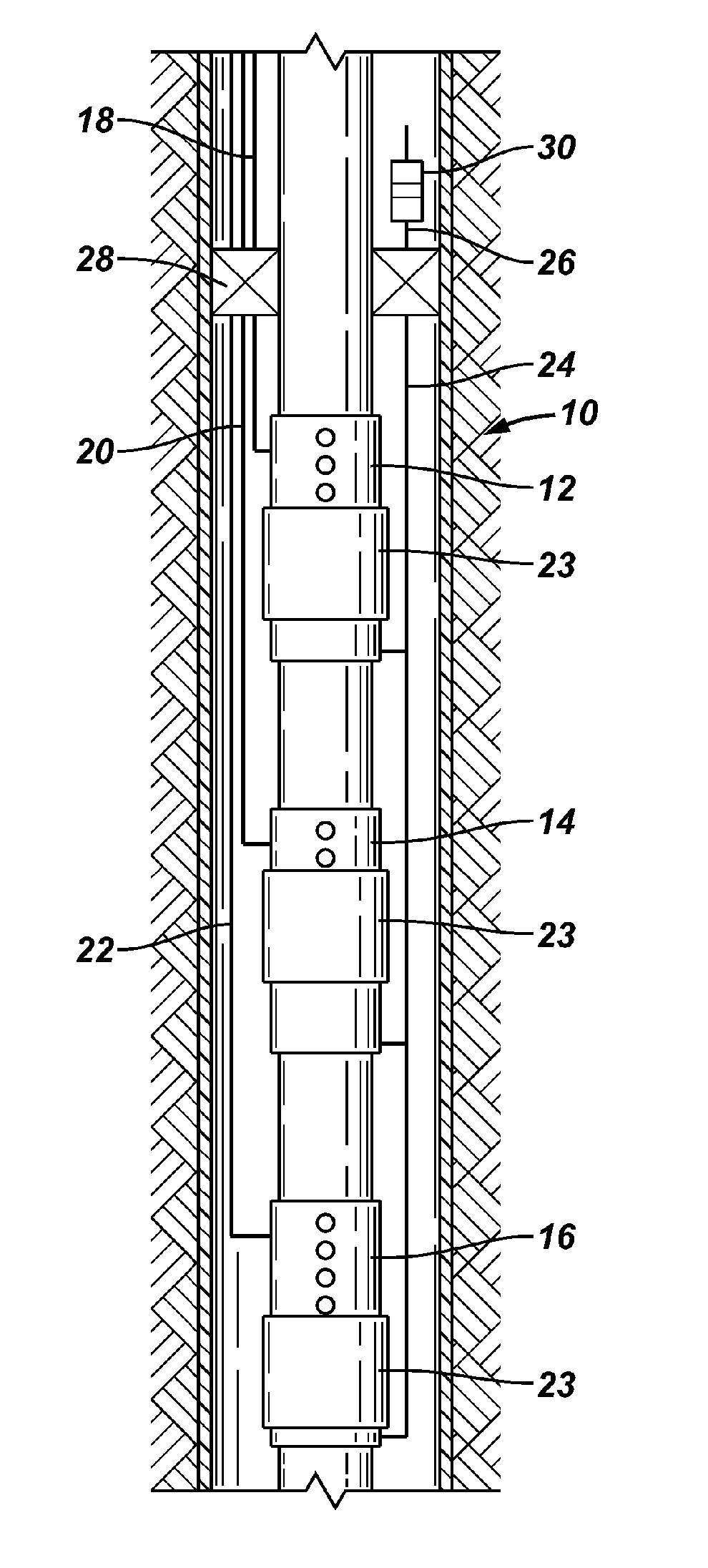
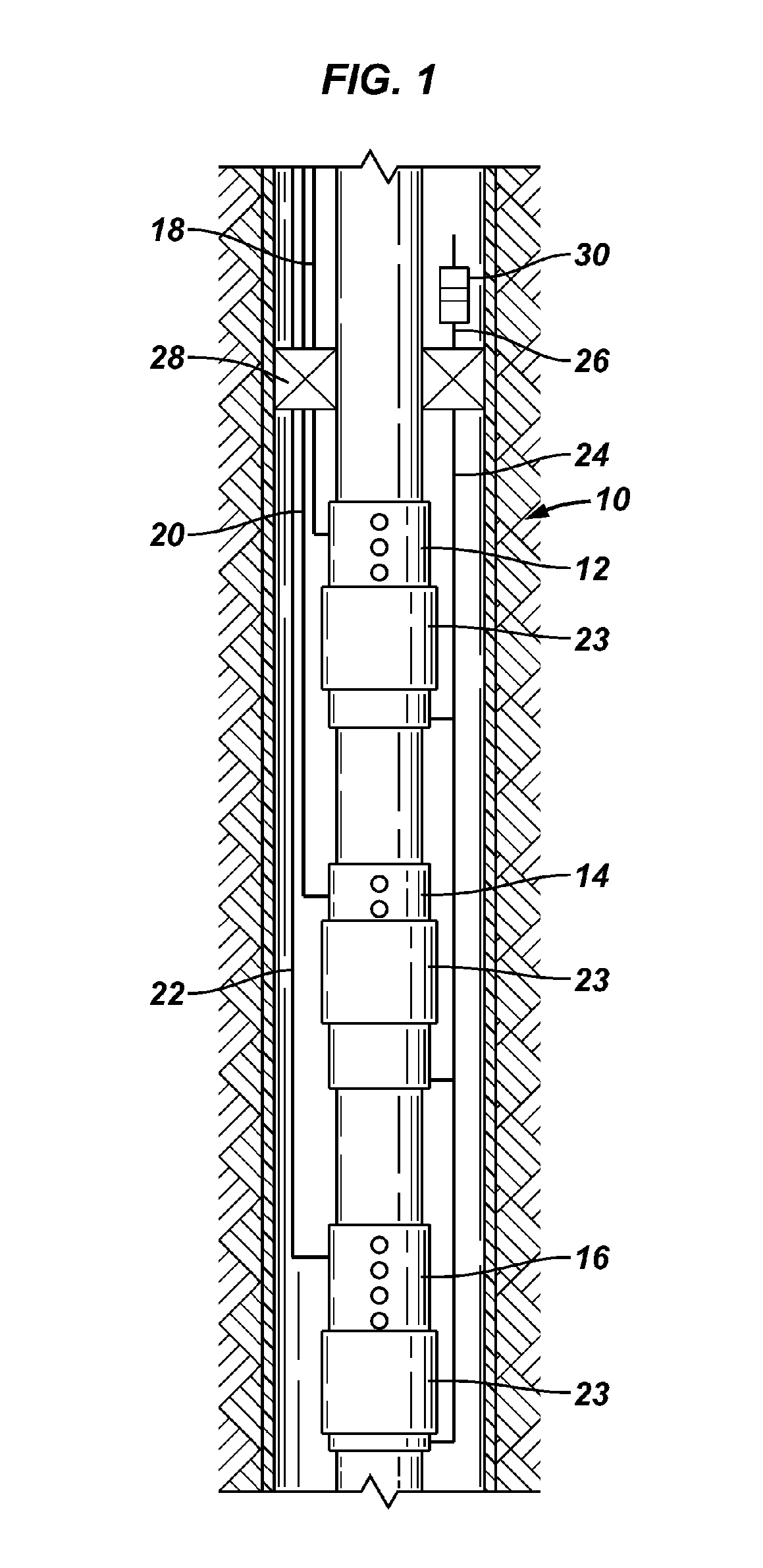
[0012]FIG. 1 shows a snorkel device 10 being used to operate a set of valves such as multi-position hydraulic valves 12, 14, 16 in a well. The valves could also be on / off valves. The invention is not limited to use on valves, however. For example, the flow control device could be a choke. Each valve 12, 14, 16 has a control line 18, 20, 22, respectively, and an indexer 23 to shift the valve to each of its various state positions. A snorkel 24 is joined to each valve 12, 14, 16. Snorkel 24 is preferably a small diameter tubing such as that commonly used for a control line. Snorkel 24 may be run to the surface, but preferably terminates at its upper end 26 just above a production packer 28. If upper end 26 of snorkel 24 terminates at some level in the well, a compensator 30 may be joined to upper end 26 to prevent co-mingling of wellbore fluids with clean hydraulic fluid. Compensator 30 allows fluid pressure in the annulus to be transferred to the hydraulic fluid in snorkel 24 without...


PUM


Abstract

The present invention provides for the operation of a downhole flow control device using a snorkel tube.

Description

BACKGROUND OF THE INVENTION[0001]1. Field of Invention[0002]The present invention pertains to downhole flow control devices, and particularly to downhole flow control devices using a common control line as a pressure source for operation.[0003]2. Related Art[0004]In running intelligent completions into subterranean wells, there are often limitations on the number of control line penetrations that can be made at the wellhead, the tubing hanger, or, in some cases, the production packer.[0005]Intelligent completions use various means to regulate flow control devices placed downhole to control production from various zones. Such flow control devices, valves, for example, can typically be fully open, partially open (choked), or fully closed. Using a plurality of such valves allows an operator to selectively receive or restrict production from different zones. A simple version of such a flow control device would typically have two control lines, one acting on either side of a piston. When...

Claims


Application Information

Patent Timeline
Patent Type & Authority Patents(United States)
IPC IPC(8): E21B34/00
CPCE21B33/1294E21B34/101E21B43/12
Inventor MACDOUGALL, THOMAS D.
Owner SCHLUMBERGER TECH CORP
Why Eureka
Try Eureka