Vehicle front end structure

a front end and vehicle technology, applied in the direction of vehicular safety arrangments, roofs, transportation and packaging, etc., can solve the problems of disfiguring the vehicle front end, imposing limitations particularly on design, etc., and achieves the effect of enhancing the rigidity of the face part, minimizing air flow resistance, and enhancing the rigidity of the face support itsel

Inactive Publication Date: 2008-11-25
MAZDA MOTOR CORP
View PDF4 Cites 38 Cited by
  • Summary
  • Abstract
  • Description
  • Claims
  • Application Information

AI Technical Summary

Benefits of technology

[0010]An object of the present invention is to provide a vehicle front end structure that has a large front grille inclined so that its lower side is located frontwardly of its upper side and formed substantially in an arcuate shape as viewed from above, in which the front grille can be prevented from hanging down owing to its own weight.

Problems solved by technology

Such a structure, however, imposes limitations particularly on the design for the front grille.
If the front grille has an inclined configuration so that its lower side is located frontwardly of its upper side, such a support structure consisting essentially of suspending the front grille from above as in the former structure cannot sufficiently bear the weight of the front grille.
If only part of the front grille thus hangs down, an unsightly gap is created between the front grille and a bonnet located thereabove, which disfigures the vehicle front end.

Method used


Image

  • Vehicle front end structure
  • Vehicle front end structure
  • Vehicle front end structure

Examples


embodiment 1

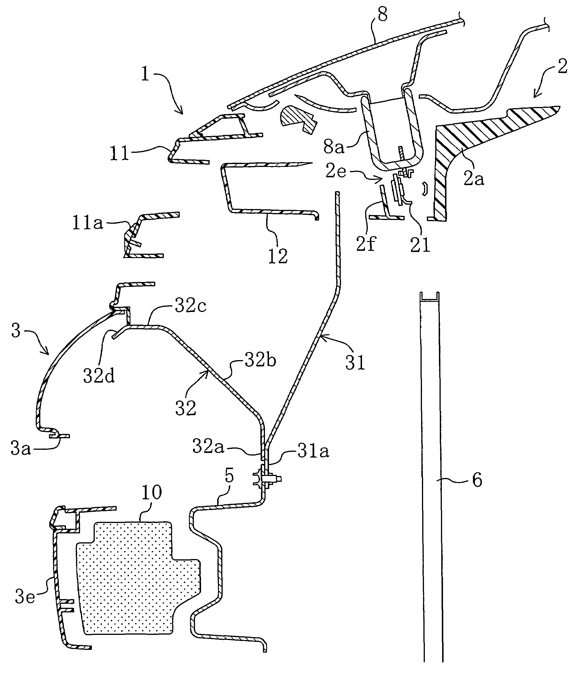
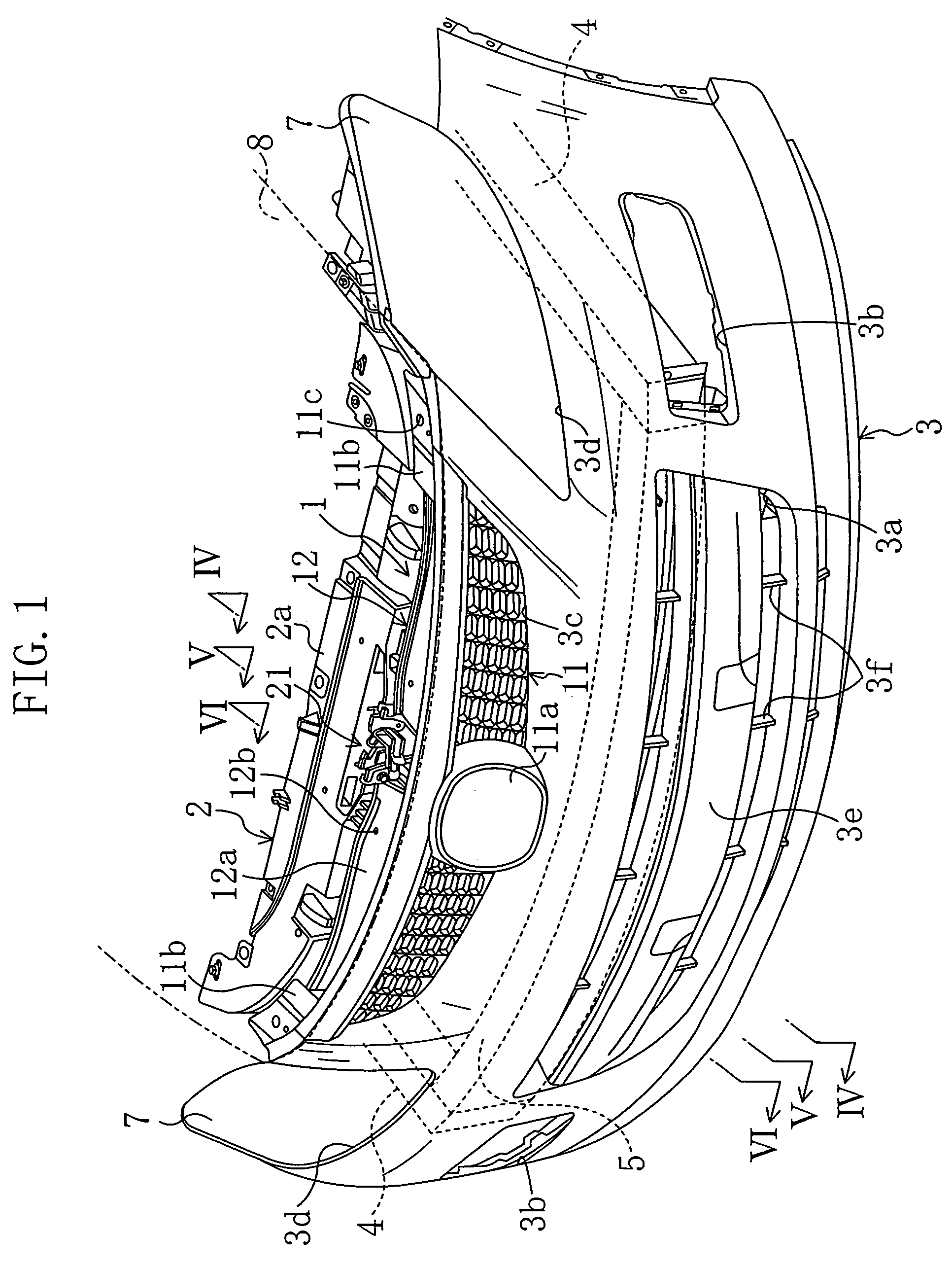
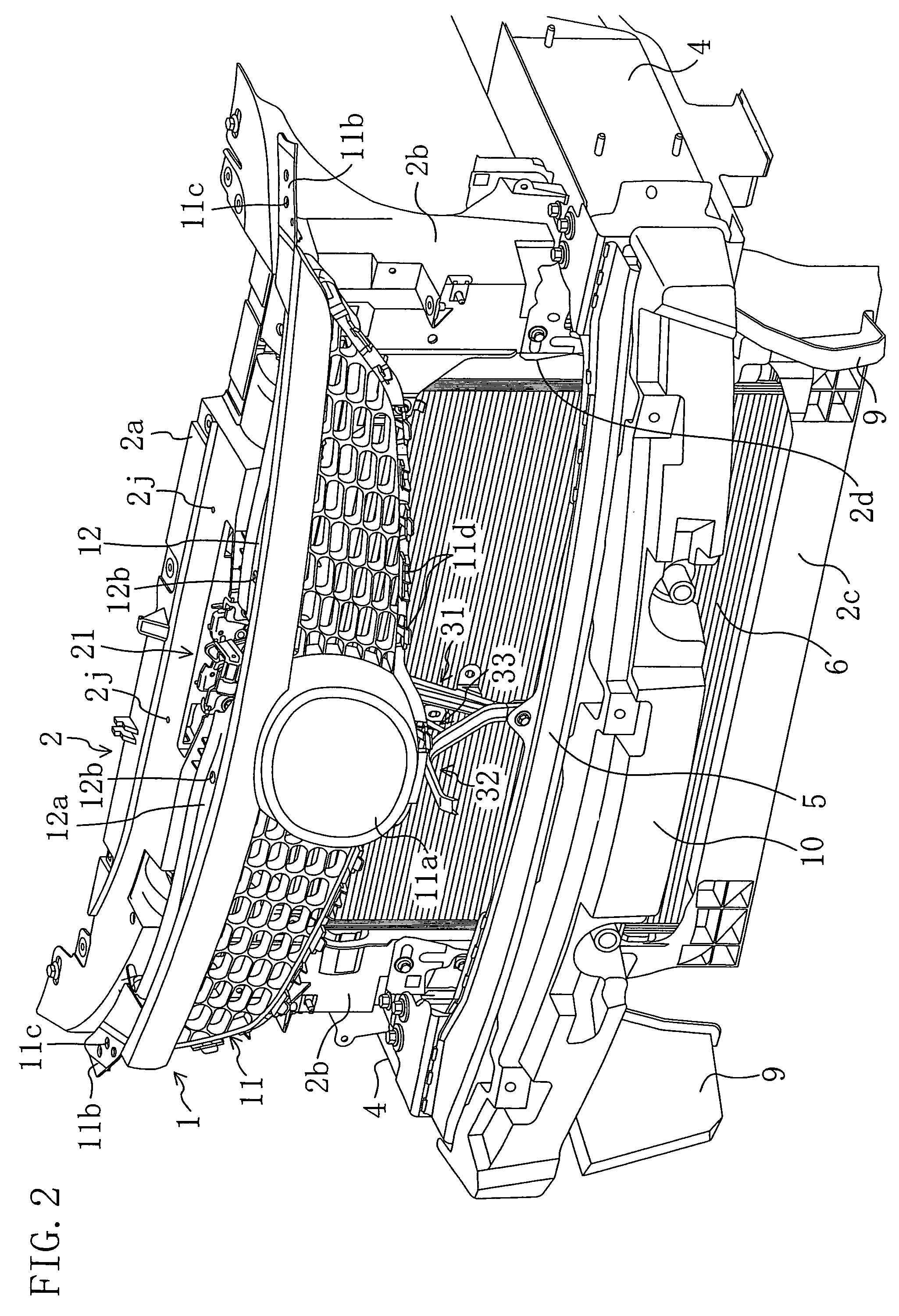
[0074]FIG. 1 shows a vehicle front end structure according to Embodiment 1 of the present invention. Specifically, FIG. 1 schematically illustrates essential components of the vehicle front end structure, such as a front grille 1, a shroud panel 2 and a bumper face 3 (a front bumper face). The rest of the vehicle front end structure, such as an engine, is not given in the figure.

[0075]The bumper face 3 is constituted by a resin plate material molded in a given shape and disposed to cover the front end of the vehicle. A lower part of the bumper face 3 has a bumper face opening 3a formed as a vent in the middle thereof, and has fog lamp openings 3b and 3b which are formed to the right and left of the bumper face opening 3a and in which their associated fog lamps are placed. The top end of the bumper face 3 has a grille recess 3c formed in the middle thereof and the front grille 1 is placed in the grille recess 3c. The top end of the bumper face 3 also has head lamp recesses 3d and 3d ...

embodiment 2

[0118]FIGS. 13 to 15 show a front view, a back view and a rear perspective view of a vehicle front end structure according to Embodiment 2 of the present invention. The vehicle front end structure according to Embodiment 2 is different from that of Embodiment 1 only in the support structure for the front grille 1. Therefore, the same parts are identified by the same reference numerals and a description is given only of the different points.

[0119]In this embodiment, the front face (a surface) of a bumper retainer 71 abuts on the back of the bumper face 3 to enhance the rigidity of the bumper face 3 and the bumper retainer 71 supports the front grille 1 from below. Furthermore, the bumper retainer 71 is supported by a retainer support member 75 (grille support) extending frontward and upward from the bumper beam side mounting part 31b of the center stay 31.

[0120]Specifically, as also shown in FIG. 17, the bumper retainer 71 is a resin structural member formed to conform to the bottom ...

embodiment 3

[0146]FIG. 19 shows a vehicle front end structure according to Embodiment 3 of the present invention. Specifically, FIG. 19 schematically illustrates essential components of the vehicle front end structure, such as a front grille 1, a bumper face 3 (a front bumper face) and a bonnet 8. The rest of the vehicle front end structure, such as head lights and fog lamps, is not given in the figure. The vehicle front end structure of Embodiment 3 is different from those of Embodiments 1 and 2 only in the support structure for the front grille 1 and, therefore, the same parts are identified by the same reference numerals in the following description.

[0147]The bumper face 3 is constituted by a resin plate material molded in a given shape and disposed to cover the vehicle front end. A lower part of the bumper face 3 has a bumper face opening 3a (an opening) formed as a vent in the middle thereof, and has a bumper face lower opening 3b formed as another vent below the bumper face opening 3a. Th...


PUM


Abstract

A front end structure for a vehicle comprises: a front bumper face; a shroud upper disposed to the rear of the front bumper face; a bumper beam disposed below the shroud upper to span the front ends of right and left front side frames; a center stay made of metal and spanning the shroud upper and the bumper beam; and a front grille supported at the upper side to the shroud upper and supported at the lower side to the front bumper face, the front grille is inclined so that the lower side is located frontwardly of the upper side, and the center stay is integrally provided with a grille support having a root end connected to the center stay and an abutment supporting part extending from the root end towards the bottom of the front grille to support the front grille from below. Alternatively, a front end structure for a vehicle comprises: a front bumper face; a shroud disposed to the rear of the front bumper face and including at least an upper part and right and left side parts; a front grille supported at the upper side to the shroud, supported at the lower side to the front bumper face and inclined so that the lower side is located frontwardly of the upper side; and a front grille support member including right and left mounting parts mounted to the right and left side parts of the shroud, respectively, and a shelf connecting the right and left mounting parts, formed to protrude frontward at a spanning part thereof connecting the right and left mounting parts and supporting the front grille from below.

Description

CROSS-REFERENCES TO RELATED APPLICATIONS[0001]This application claims priority under 35 USC 119 to Japanese Patent Applications Nos. 2006-42881 filed on Feb. 20, 2006, 2006-37876 filed on Feb. 15, 2006 and 2006-52891 filed on Feb. 28, 2006, the entire contents of all of which are incorporated herein by reference.BACKGROUND OF THE INVENTION[0002](a) Field of the Invention[0003]This invention relates to a front end structure for a vehicle and particularly relates to a front grille support structure.[0004](b) Description of the Related Art[0005]A front grille for a vehicle is provided as an air vent in the front end of the vehicle above a front bumper. In a known mounting structure for a front grille, such as disclosed in Published Japanese Patent Application No. H11-314552, a front grille is supported from above by suspension from a shroud upper for holding a radiator and other peripheral components and supported from below by a bumper face of a front bumper. In such a structure, in o...

Claims


Application Information

Patent Timeline
Patent Type & Authority Patents(United States)
IPC IPC(8): B60J7/00B60K13/02
CPCB60R19/52
Inventor NAKAYAMA, NOBUYUKISAKAMOTO, TOSHIO
Owner MAZDA MOTOR CORP
Why Eureka
Try Eureka