
Drum brake implement

a drum brake and implement technology, applied in the field of mechanical devices, can solve the problems of increasing the difficulty of installation and removal of vehicle drum brakes, increasing the difficulty of reassembly of the springs after shoe replacement, and increasing the difficulty of installation and removal

Inactive Publication Date: 2008-12-02
MAYHEW STEEL PRODS
View PDF3 Cites 2 Cited by
  • Summary
  • Abstract
  • Description
  • Claims
  • Application Information

AI Technical Summary

Benefits of technology

"The present invention provides a brake maintenance implement that includes four tools: a pig tail tool, a socket tool, a return spring installer tool, and a retainer pivotally connecting these tools. The pig tail tool has an inwardly extending tab that selectively engages the return spring installer tool to prevent rotation. The implement can be stacked and pivotally connected to a retainer, making it easy to use. The technical effects of this invention include improved brake maintenance efficiency and ease of use."

Problems solved by technology

The installation and removal of vehicle drum brakes is oftentimes difficult and time consuming.
Still further, reassembly of the springs after shoe replacement requires still additional tools.
This is made even more complicated due to the difficulty of working with springs under tension or compression.

Method used


Image

  • Drum brake implement
  • Drum brake implement
  • Drum brake implement

Examples


Embodiment Construction

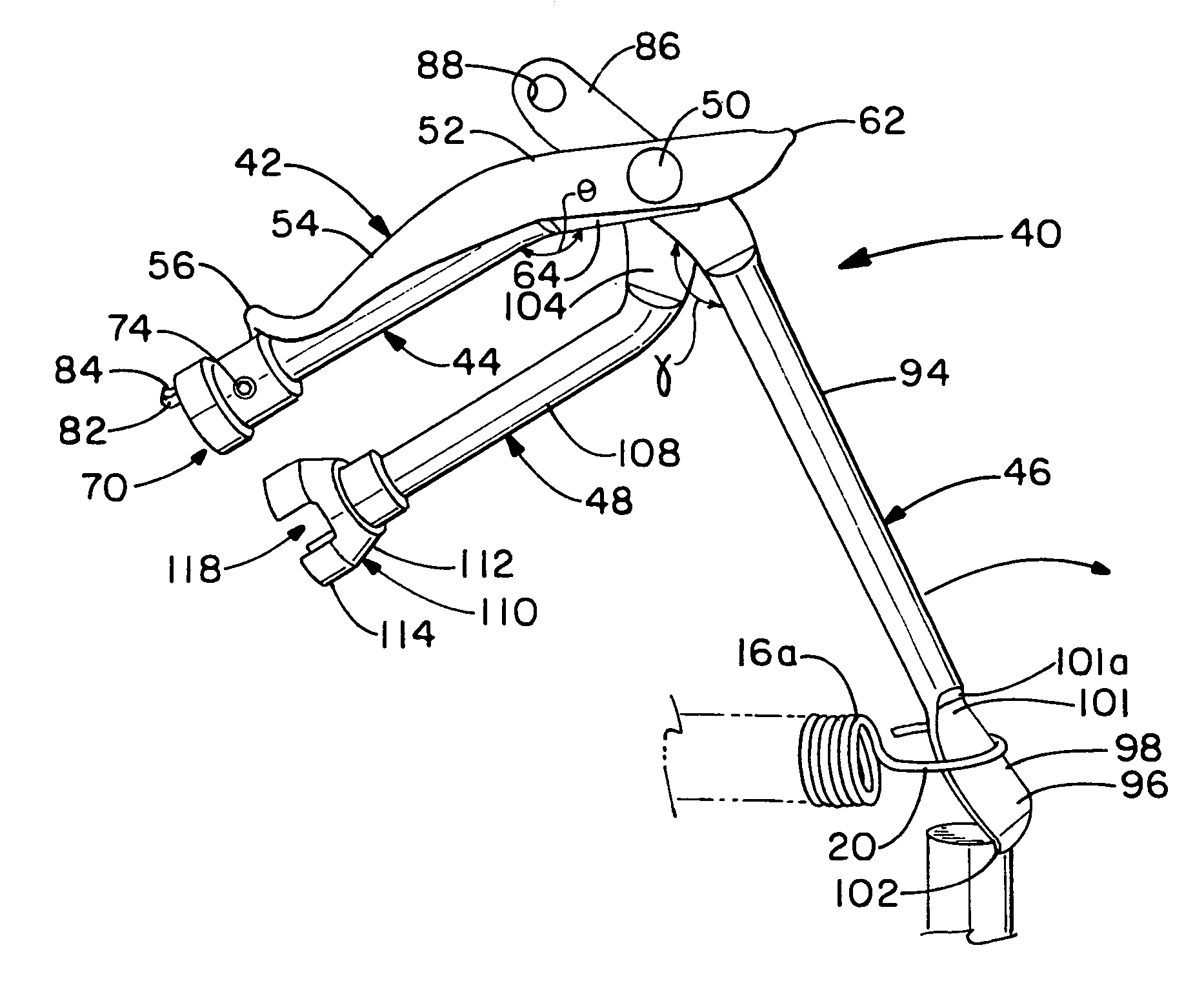
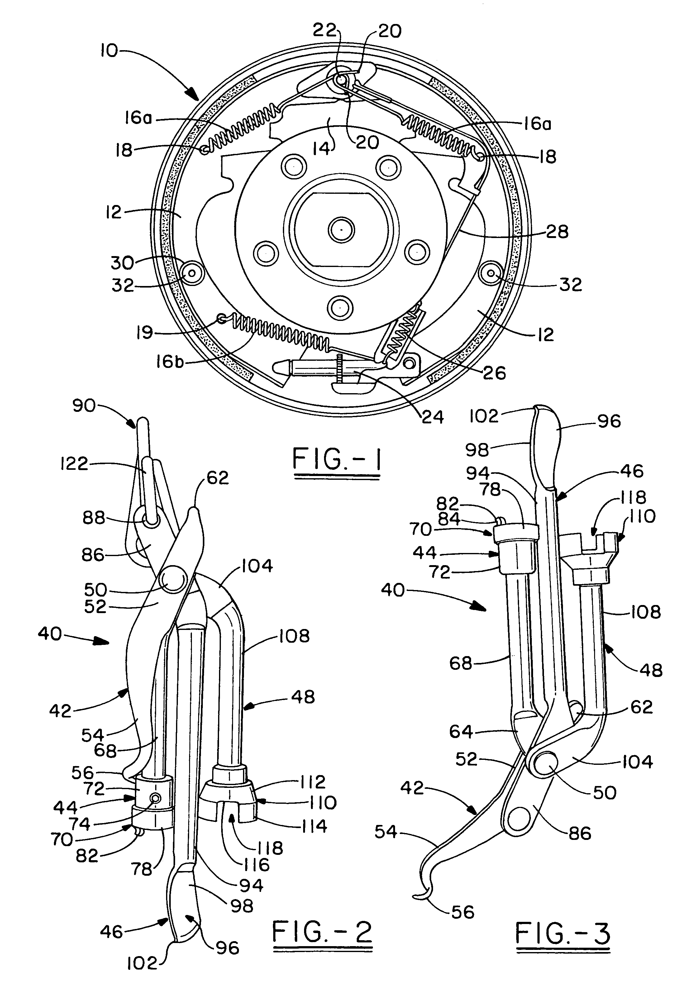
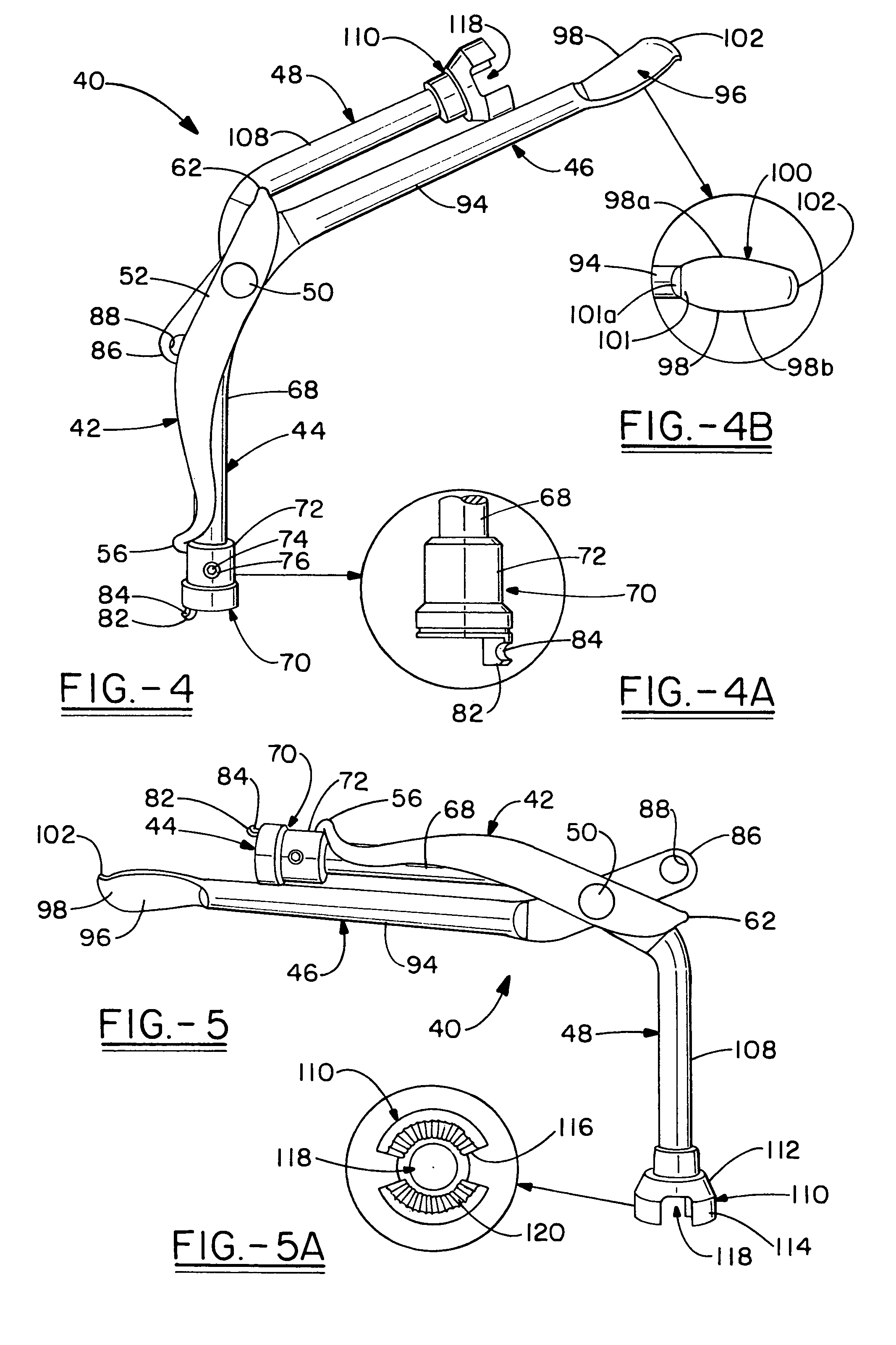
[0020]With reference to FIGS. 1-8, a preferred drum brake maintenance implement according to this invention is shown and designated generally by the numeral 40. Implement 40 generally includes a first tool 42, second tool 44, third tool 46 and fourth tool 48 which are coupled together via a retainer 50. Retainer 50 may allow for rotation of the tools relative to each other so that each tool may be separated from the others and placed in an operating position. To that end, retainer 50 may act as a pivot and be in the form of a pin, bolt, rivet or other structure that joins the tools yet allows them to rotate.

[0021]With reference to FIGS. 2-3, first tool 42, which may be referred to as a “pig tail tool”, includes a body portion 52. To reduce the bulk of implement 40, body portion 52 may be made flat. Body portion 52 terminates at a tapered portion 54, which may be disposed at an angle relative to body portion 52. Tapered portion 54 transitions to a first tool end 56 which is a spiral,...


PUM

PropertyMeasurementUnit
angleaaaaaaaaaa
angleaaaaaaaaaa
shaft angleaaaaaaaaaa

Abstract

An implement including a first tool having a first tool end in the form of a pig tail. The first tool includes an inwardly extending tab. A second tool is adjacent the first tool and has a second tool end adapted to receive a pin and includes a curved finger carried by the second tool end. A third tool is adjacent the second tool and has a third tool end which includes a sliding surface. A fourth tool is adjacent the third tool and has a fourth tool end which provides a ribbed interior surface adapted to engage a cap. Each tool is pivotally connected to a cylindrical retaining means, the tab selectively engaging the third tool, wherein when the tab engages the third tool, relative rotation is prevented.

Description

TECHNICAL FIELD[0001]The present invention generally relates to a mechanic's implement used in the assembly and disassembly of drum brakes. More particularly, this invention relates to an implement which incorporates all of the tools necessary for drum brake maintenance in a single pivoting assembly.BACKGROUND OF THE INVENTION[0002]The installation and removal of vehicle drum brakes is oftentimes difficult and time consuming. Unlike the more simple disc brakes, drum brakes employ a complicated set of springs and retaining pins to hold together and bias the brake components. Referring to FIG. 1, an exemplary drum brake assembly 10 is disclosed. The drum brake assembly 10 includes a pair of opposed shoes 12 which are generally crescent shaped and pivotally secured to a backing plate 14. A braking force is applied when shoes 12 are forced outward and engage the interior of a rotatable drum. A number of springs 16, also referred to as return or retracting springs 16a or adjustor springs...

Claims


Application Information

Patent Timeline
Patent Type & Authority Patents(United States)
IPC IPC(8): B25B25/00B23P19/04
CPCF16D65/0043Y10T29/53613
Inventor KLISKEY, ROGER
Owner MAYHEW STEEL PRODS
Learn More