Crimping tool with quick-change crimp head for sealing and electrically crimping electrical contacts to insulated wire

a crimping head and crimping tool technology, applied in the field of crimping tools, can solve the problems of affecting the performance affecting the performance of previous crimping equipment, so as to prevent the performance of a second crimping action, and the effect of quick and easy insertion and removal

Inactive Publication Date: 2008-12-09
TRI STAR TECH
View PDF14 Cites 15 Cited by
  • Summary
  • Abstract
  • Description
  • Claims
  • Application Information

AI Technical Summary

Benefits of technology

[0006]The present invention has been developed in response to the current state of the art, and in particular, in response to these and other problems and needs that have not been fully or completely solved by currently available crimping tools. Thus, it is an overall object of the present invention to effectively resolve at least the problems and shortcomings identified herein. In particular, it is an object of the present invention to provide a crimper tool wherein a crimping die holder is configured for quick and easy insertion and removal in a base unit. It is also an object of the present invention to provide a crimper tool that crimp forms a reliable hermetic seal between a contact and the insulative coating on a single or multi-strand core wire. It is a further object of the present invention to provide a crimper tool with an adjustable crimp depth. It is a further object of the present invention to provide a crimper tool with a sensor system that prevents the performance of a second crimping action on the same contact-wire assembly. Finally, it is an object of the present invention to provide a crimper tool wherein a crimping die holder is configured for quick and easy insertion and removal from a base unit, a sensor system prevents unintentionally performing two crimping cycles on the same contact and monitors the depth of the electrical crimp, and the crimping operation forms a substantially cylindrical hermetic crimp seal between a contact and the insulative coating on a single or multi-strand core wire. Embodiments of the present invention are particularly suitable for use in attaching contacts to single or multi-strand aluminum wire.
[0007]A preferred embodiment of the quick disconnect assembly according to the present invention comprises a bench mounted or hand-held crimping tool. A quick-change crimp head crimps a contact to a single or multi-strand core aluminum alloy wire to form both a reliable hermetic seal and good electrical continuity between the contact and the wire. The quick-change crimp head preferably slips axially in and out of a receptacle in a base unit. Between crimp cycles, the quick-change crimp head is generally held in the receptacle by the action of a latching or locking mechanism. The actuating mechanism for the quick-change crimp head is preferably located in the base unit. This placement of the actuating mechanism minimizes the mass, expense, and complexity of the quick-change crimp head. It also allows for very robust and flexible actuating mechanisms that are capable of accurately accommodating a wide range of wire gauges from, for example, 26 gauge or smaller to 12 gauge or larger. Typically, a separate quick-change crimp head is kept available for at least each wire gauge, and, if required, for each style of contact. When a particular wire gauge or contact style is to be crimped, the proper quick-change crimp head is selected and inserted into the receptacle. The mounting of a quick-change crimp head in a base unit by an experienced operator generally requires less than approximately a minute, and preferably, less than approximately 30 seconds. The actuating mechanism engages the quick-change crimp head when it is properly positioned in the receptacle portion of the base unit. A sensor system prevents accidentally applying two crimping cycles to the same contact-wire assembly and verifies continuity-crimp quality. Such sensor systems are conventional in the crimping art. The accidental application of more than one crimping cycle is conveniently prevented by requiring that the system be reset before it will perform another cycle. Crimp continuity is conveniently assured by providing a signal (audible, visual, tactile, or otherwise) to alert the operator if the contact is not indented to a predetermined depth during the cycle.
[0011]When a crimp sensor detects that the proper depth of electrical crimp indentation has been reached, the actuating mechanism counter-rotates the cam ring(s) to allow the dies to withdraw from crimping engagement with the contact-wire assembly. This completes the cycle. The sensor prevents a second cycle from being inadvertently initiated until the system is armed again. The crimped contact-wire assembly is withdrawn from the contact holder. The sensor will rearm the system for another cycle when it senses a contact in the proper position in the contact holder.

Problems solved by technology

Aluminum and its alloys, for example, are typically susceptible to corrosion if the coating of insulation is broken.
Previous expedients were generally less than completely satisfactory because the crimp formed seals between the coating and the contact often failed.
Also, the previous crimping equipment was generally time consuming to work with because it was difficult and time consuming to change crimping dies to accommodate different gauges of wire, crimper tool malfunctions, or the like.
Such previous equipment was generally incapable of accommodating a full range of wire gauges with one tool.

Method used


Image

  • Crimping tool with quick-change crimp head for sealing and electrically crimping electrical contacts to insulated wire
  • Crimping tool with quick-change crimp head for sealing and electrically crimping electrical contacts to insulated wire
  • Crimping tool with quick-change crimp head for sealing and electrically crimping electrical contacts to insulated wire

Examples


Embodiment Construction

[0058]Referring now to the drawings wherein like reference numerals designate identical or corresponding parts throughout the several views. It is to be understood that the drawings are diagrammatic and schematic representations of various embodiments of the invention, and are not to be construed as limiting the invention in any way. The use of words and phrases herein with reference to specific embodiments is not intended to limit the meanings of such words and phrases to those specific embodiments. Words and phrases herein are intended to have their ordinary meanings, unless a specific definition is set forth at length herein.

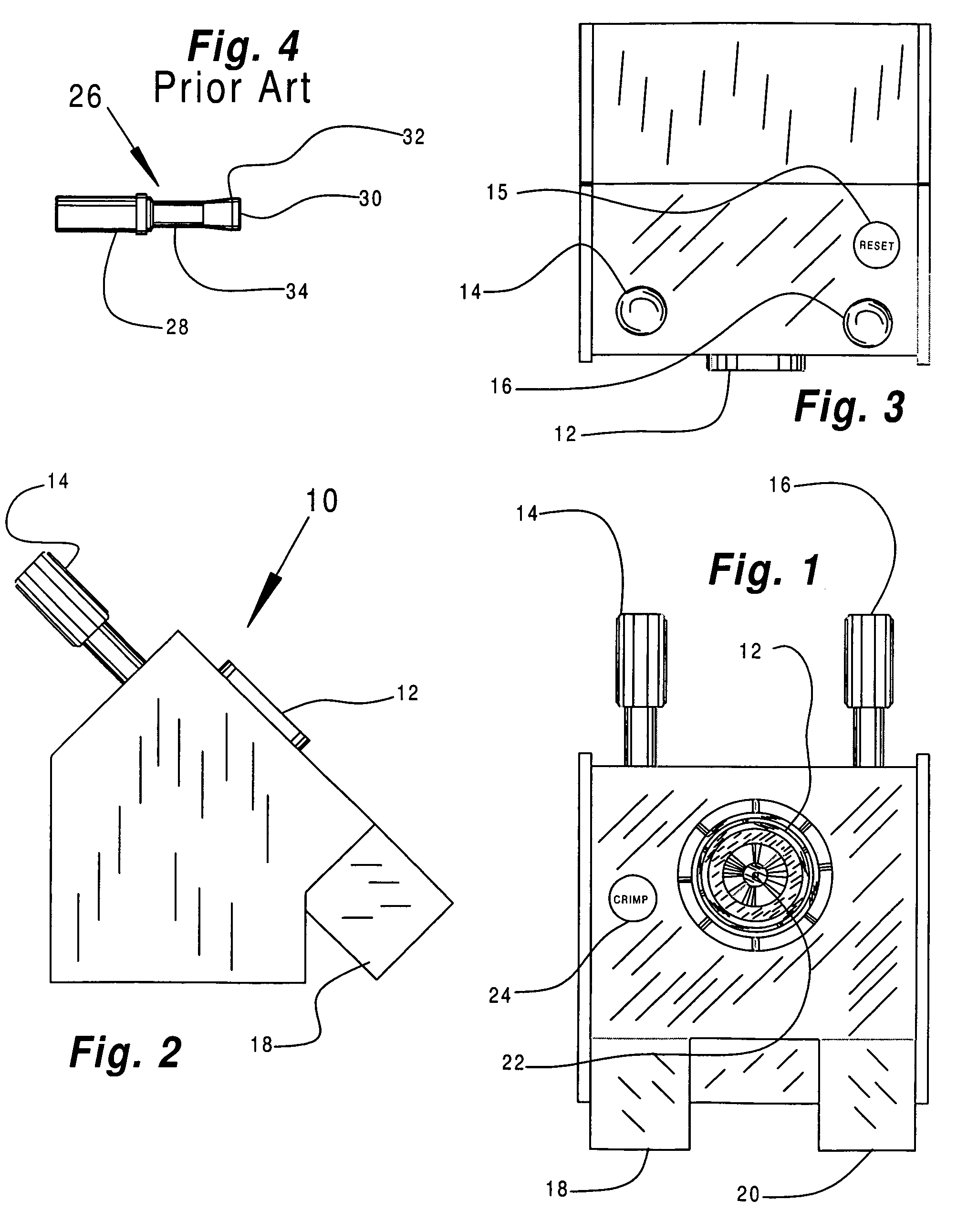
[0059]For purposes of illustration, a bench mounted embodiment of the invention has been shown. It will be understood by those skilled in the art that hand held embodiments of the present invention may be used for lighter gauges, for example, smaller than approximately 18 gauge. For heavier gauges, for example, 14 gauge and heavier, it preferable to use a ben...


PUM

PropertyMeasurementUnit
depthaaaaaaaaaa
atmospheric pressureaaaaaaaaaa
pressureaaaaaaaaaa

Abstract

A crimping tool with a quick-change crimp head for sealing and electrically crimping electrical contacts to insulated wires. The crimping tool includes a base unit with a receptacle that is configured to actuate and removably and replaceably receive the quick-change crimp head. A crimping die holder body includes a plurality of crimp-seal and continuity-crimping dies. These dies are mounted for movement in the crimping die holder body between an open configuration and a fully crimped configuration. The crimp-seal dies have arcuate die faces that define a substantially closed generally cylindrical form when the dies are in the fully crimped configuration. Actuators are mounted in the base unit. The actuators are adapted to cause the dies to move in the body. A sensor system is configured to prevent the crimping tool from unintentionally repeating a crimping operation on the electrical contact, and to verify continuity-crimp depth of indentation.

Description

BACKGROUND OF THE INVENTION[0001]1. Field of the Invention[0002]The invention relates in general to methods and devices for mounting an electrical contact to an insulated multi-strand or single strand wire and, more particularly, embodiments of the present invention relate to improvements in methods and devices for mounting contacts onto insulated multi-strand and single strand wires by indenting the contact into the multi-strand or solid wire to form an electrical contact, and crimping the contact around the insulation to form an hermetic seal between the insulation and the contact in one crimping cycle.[0003]2. Description of the Prior Art[0004]Multi-strand and single strand aluminum alloy wires have been widely used for various electrical wiring purposes, and recently in aircraft and aerospace applications where a reduction in the weight of the wiring is achieved by such use. Solid or multi-strand aluminum wires typically include a core of aluminum alloy metal strand(s) surrounde...

Claims


Application Information

Patent Timeline
Patent Type & Authority Patents(United States)
IPC IPC(8): H01R43/00
CPCH01R43/0424H01R43/0585Y10T29/53235Y10T29/53257Y10T29/53226Y10T29/53283Y10T29/53213
Inventor SCHWARTZMAN, SIMONKERNER, ALEX
Owner TRI STAR TECH
Why Eureka
Try Eureka