Wedge mechanism

a wedge mechanism and motion-transformation technology, applied in the direction of rod connections, couplings, ways, etc., can solve the problems of increasing the size and weight of the mechanism, requiring two-stage mechanisms, and further increasing the size, weight, and cost of the device employing wedge mechanisms, so as to improve the device, improve the device, and reduce the cos

Inactive Publication Date: 2008-12-16
SUCCESSOR TRUSTEE OF THE EUGENE RIVIN LIVING TRUST +2
View PDF10 Cites 0 Cited by
  • Summary
  • Abstract
  • Description
  • Claims
  • Application Information

AI Technical Summary

Benefits of technology

[0009]The present invention further improves on the prior art by providing a wedge mechanism which has high mechanical advantage while not requiring lubrication.
[0010]The present invention further improves the prior art by providing a wedge mechanism which is constructed as a solid-state mechanical device insensitive to external shocks, vibrations, and requires only a minimal maintenance.
[0011]The present invention improves and simplifies the devices employing wedge mechanisms by making the wedge mechanism largely insensitive to contamination by environmental contaminants such as water and other fluids, dirt, abrasive particles, etc.
[0012]The present invention further improves the devices employing wedge mechanisms by eliminating the need for making contact surfaces in wedge mechanism with high hardness and high geometrical accuracy of their contact surfaces, and by allowing use of light materials for structural parts of the wedge mechanisms.

Problems solved by technology

Even worse deterioration from the ideal efficiency / mechanical advantage would develop for more realistic larger values of f. As a result, wedge angles smaller than α<˜5° are seldom used in practical designs and relatively high driving (input) forces should be used, thus increasing size and weight of the mechanisms, requiring two-stage mechanisms, etc.
The noted above lack of mobility in the mechanism at small displacements due to static friction forces, leads to a need to increase stiffness of the mechanism and thus further increase its size, weight, and cost of the devices employing wedge mechanisms.
The contact surfaces have to be well lubricated and well protected since any scratches would result in increased friction and reduced efficiency.
Consequently, the rated values of the mechanical advantage (clamping force) may change significantly depending on the vibratory environment, thus reducing consistency and reliability of these important mechanisms.
However, such designs require even better materials and heat treatment, higher accuracies, and are more bulky and more expensive. better materials and heat treatment, higher accuracies, and are more bulky and more expensive.

Method used


Image

  • Wedge mechanism
  • Wedge mechanism
  • Wedge mechanism

Examples


Embodiment Construction

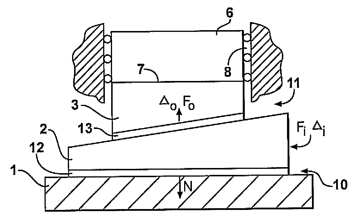
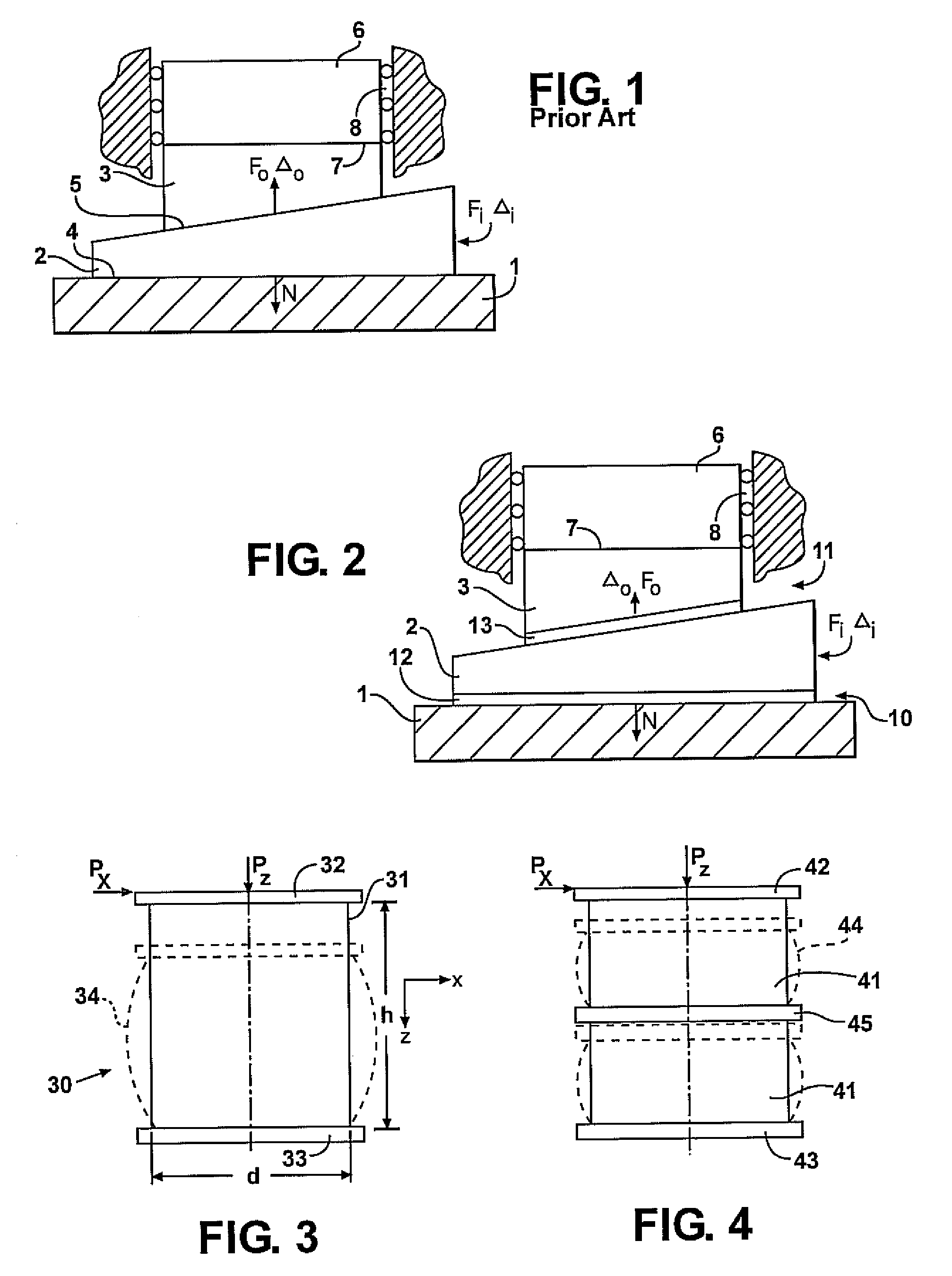
[0022]Referring to FIG. 2, the shown wedge mechanism comprises the same basic mechanical members as the prior art wedge mechanism depicted in FIG. 1, namely base member 1, movable wedge member 2, and output member 3 which can be interacting via surface contact 7 with work organ 6 and whose motion can be constrained by guideways 8. The wedge mechanism in FIG. 2 differs from the prior art wedge mechanism in FIG. 1 by designs of a first surface contact area 10 between base member 1 and the wedge member 2, which is movable along an axis in the direction of an applied force Fi to vary the separation between the surface contact area 10 and of a second surface contact area 11 disposed between movable wedge member 2 and output member 3. The wedge member 2 has a third contact surface 15 opposed to and conforming with the first contact surface 10, and a fourth contact surface 16 opposed to and conforming with the second contact surface 11. The motion of the output member 3 along the axis in t...


PUM

PropertyMeasurementUnit
Poisson's ratiosaaaaaaaaaa
thicknessaaaaaaaaaa
mechanicalaaaaaaaaaa

Abstract

A mechanical wedge mechanism comprising base member, output member, and movable wedge member in which frictional connections between mutually movable mechanical members are replaced with shear deformations in elastomeric shims connecting respective surfaces of the members, thus effectively reducing frictional losses in the mechanism.

Description

FIELD OF THE INVENTION[0001]The present invention relates to force- and motion-transformation mechanisms.BACKGROUND OF THE INVENTION[0002]Wedge mechanisms are widely used in mechanical devices. The most important applications of the wedge mechanisms are as force amplifiers Thus, the wedge mechanisms and their analogs are universally used in clamping mechanisms wherein relatively small forces applied manually or by means of relatively small and low power motors / actuators can be transformed into much larger clamping forces. The basic conventional wedge mechanism (the Prior Art) in FIG. 1 comprises base member 1, movable wedge member 2, and output member 3. These members have sliding frictional contacts along flat or curved conformal surfaces 4 between members 1 and 2 and along flat or curved conformal surfaces 5 between members 2 and 3. Usually the respective contact surfaces of members 1 and 2 and of members 2 and 3 are separated by a thinner or thicker layer of a lubricating materia...

Claims


Application Information

Patent Timeline
Patent Type & Authority Patents(United States)
IPC IPC(8): F16F1/38E01C11/02B23B31/117B25B5/08F16B2/14
CPCB23B31/1175B23B31/1177B25B5/08F16B2/14Y10T403/458Y10T403/7066Y10T403/457Y10T409/30952Y10T403/45Y10T403/455Y10T403/54
Inventor RIVIN, EVGENY I.
Owner SUCCESSOR TRUSTEE OF THE EUGENE RIVIN LIVING TRUST
Why Eureka
Try Eureka