Rose gear for external fixation clamp

a technology of external fixation system and rose gear, which is applied in the field of mechanism of manipulating external fixation system, can solve the problems of limiting the configuration of gear design and external fixation system using rose gear, and unable to allow certain adjustment and/or pivoting, etc., and achieves high mechanical advantag

Active Publication Date: 2015-11-17
STRYKER EURO OPERATIONS HLDG LLC
View PDF50 Cites 0 Cited by
  • Summary
  • Abstract
  • Description
  • Claims
  • Application Information

AI Technical Summary

Benefits of technology

[0007]The present invention is for a novel “rose” gear design. The rose gear disclosed herein has a thread profile on a conical section of an actuation member. The gear design retains the self locking nature and high mechanical advantage of a worm drive while allowing for an angled driving gear. The gear design disclosed herein allows for an angled worm. The rotation of the rose gear drives the gear mated to it. This gear can either be a normal gear, rack, or threaded rod, resulting in both linear as well as rotational motion.
[0009]In one embodiment according to this first aspect of the present invention, rotation of the actuation portion of the actuation member about the central longitudinal axis thereof in a second radial direction opposite the first radial direction causes the housing to translate along the central longitudinal axis of the elongate rod in a second direction opposite the first direction.

Problems solved by technology

Existing fixation systems on the market have many components thereof that are static and do not allow for certain adjustment and / or pivoting.
Lack of flexibility in a fixation system may restrict attachment to certain bone areas at certain angles as well as restrict motion of the portion of the body that the external fixation system is being attached to in order to correct.
Because of such lack of flexibility, such systems may make it more difficult for the physician to achieve an optimal clinical outcome.
This limits the configuration of gear designs as well as the configuration of external fixation systems using these gears.
Clutches or ratchets may be used to prevent backdrive; however, the addition of these devices increases the number of components needed to provide or restrict the motion of such gears.

Method used


Image

  • Rose gear for external fixation clamp
  • Rose gear for external fixation clamp
  • Rose gear for external fixation clamp

Examples


Embodiment Construction

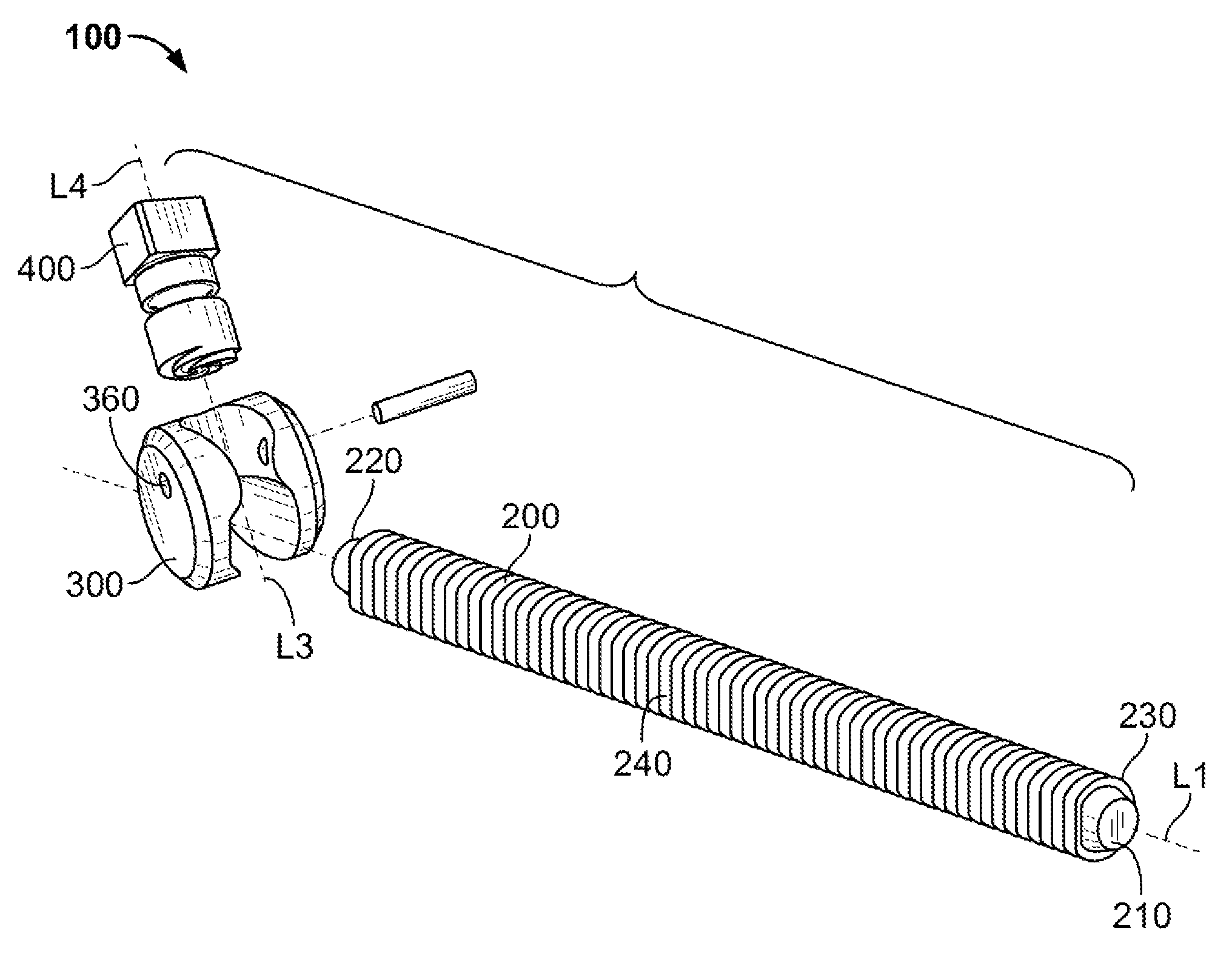
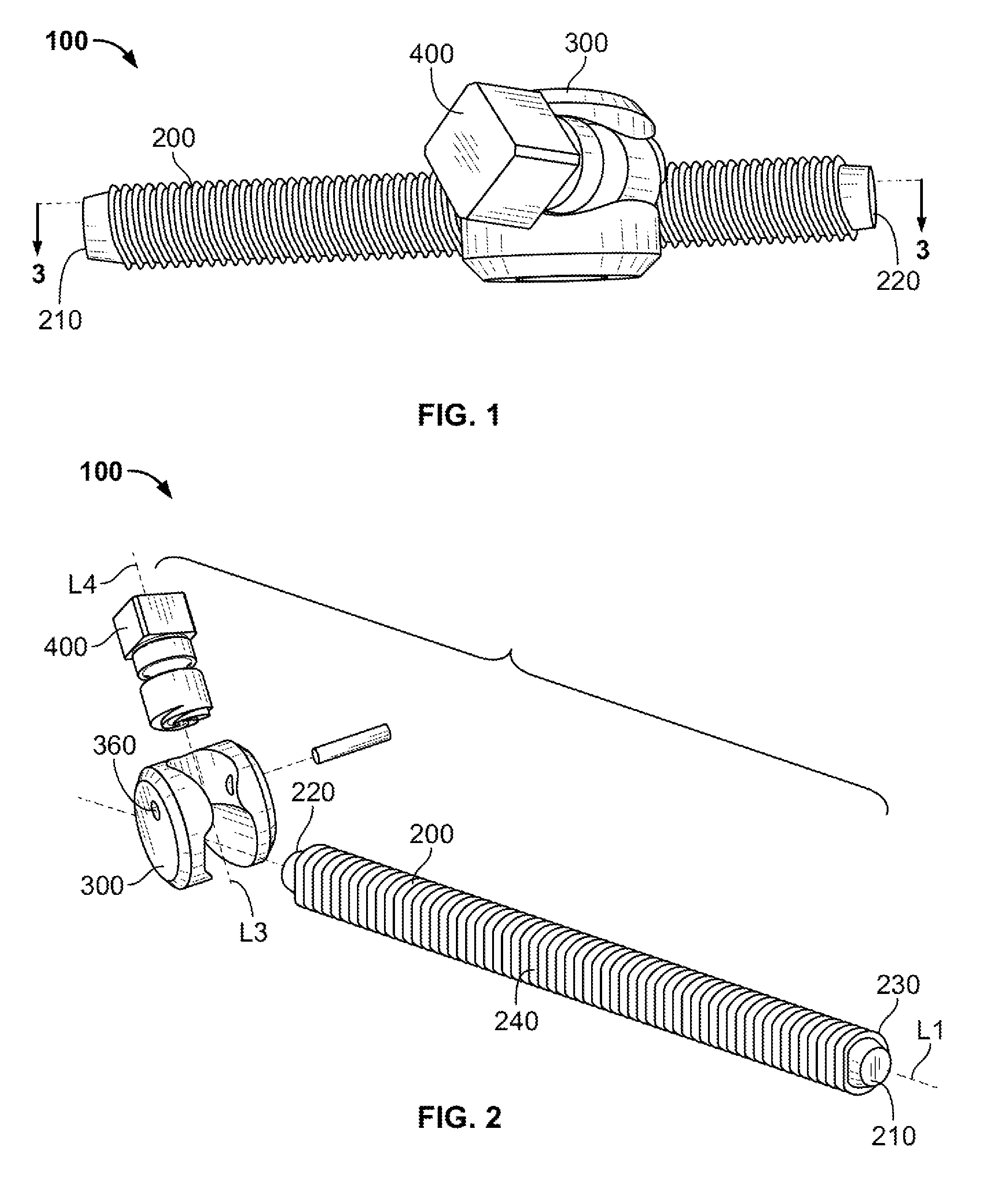
[0032]Referring to FIGS. 1-6, there is shown an embodiment of an external fixation device 100 having an elongate rod 200, a housing 300 and an actuation member 400.

[0033]As shown in FIGS. 1 and 2, elongate rod 200 has a distal end 210 and a proximal end 220 and is threaded along at least a portion of its length between the distal and proximal ends 210, 220 thereof. Elongate rod 200 has a longitudinal axis L1. The circumference of elongate rod 200 has a circular portion 230 and a flat portion 240. The distal and proximal ends 210, 220 are preferably chamfered or radiused such that elongate rod 200 does not have sharp ends. The chamfered or radiused ends of elongate rod 200 preferably aid in the coupling of additional external fixation device constructs to external fixation device 100. Such additional constructs are described later herein.

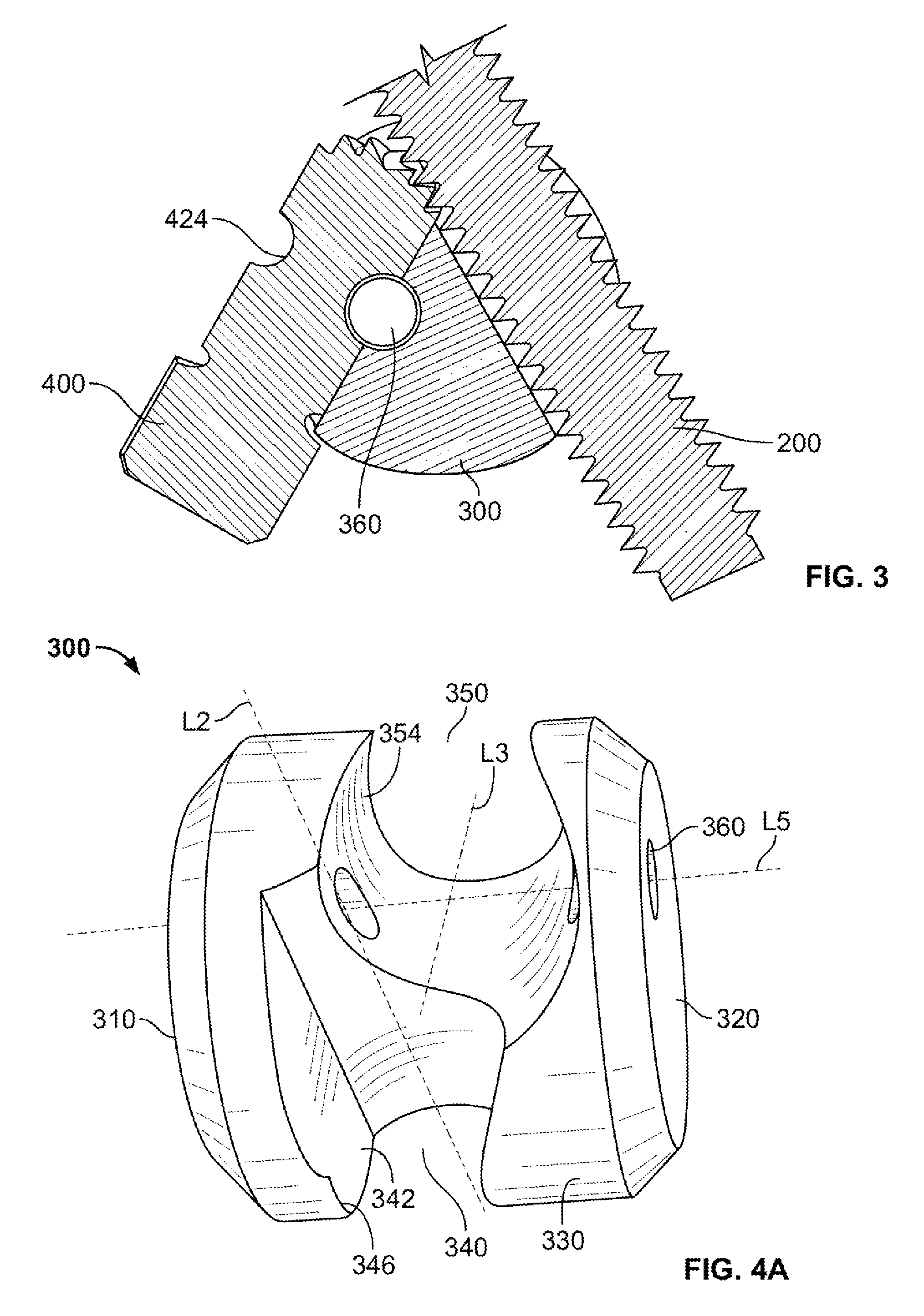
[0034]FIGS. 4A-4C show several views of housing 300. Housing 300 includes first and second side surfaces 310, 320 and a generally rounded outer circ...


PUM


Abstract

Disclosed herein are external fixation devices including at least an elongate rod, a housing and an actuation member. The housing is coupled to the elongate rod and the actuation member is rotatably coupled to the housing such that a central longitudinal axis of the actuation member is angled and offset with respect to a central longitudinal axis of the elongate rod. Rotation of an actuation portion of the actuation member about the central longitudinal axis thereof in a first radial direction causes the housing to translate along the central longitudinal axis of the elongate rod in a first direction.

Description

FIELD OF THE INVENTION[0001]The present invention relates to mechanisms for manipulating external fixation systems and in particular relates to gear mechanisms for translating a threaded rod coupled to external fixation devices in order to manipulate the devices in a desired manner.BACKGROUND OF THE INVENTION[0002]Many different types of bone deformities can be corrected using external fixation systems. Such systems generally use rings, fixation plates, threaded rods or struts for manipulation, angulation, and translation of the bone deformities.[0003]Existing fixation systems on the market have many components thereof that are static and do not allow for certain adjustment and / or pivoting. Lack of flexibility in a fixation system may restrict attachment to certain bone areas at certain angles as well as restrict motion of the portion of the body that the external fixation system is being attached to in order to correct. Because of such lack of flexibility, such systems may make it ...

Claims


Application Information

Patent Timeline
Patent Type & Authority Patents(United States)
IPC IPC(8): A61B17/00A61B17/66A61B17/64
CPCA61B17/66A61B17/6466A61B17/6475
Inventor CHANG, ERICMURNER, BEAT
Owner STRYKER EURO OPERATIONS HLDG LLC
Why Eureka
Try Eureka