Connector assembly with variable axial assist

a technology of axial assist and connector, which is applied in the direction of coupling device connection, coupling/disassembly parts, electrical apparatus, etc., can solve the problems of reducing the total number of terminals in the connector, cumbersome multi-step mating process for assemblers, etc., and achieves high mechanical advantage, reduce peak mating force, and high mate-assist system friction

Active Publication Date: 2019-01-22
APTIV TECH LTD
View PDF17 Cites 0 Cited by
  • Summary
  • Abstract
  • Description
  • Claims
  • Application Information

AI Technical Summary

Benefits of technology

[0004]As described herein, the problem of high mate-assist system friction and the reduction of the peak mating-force with a variable mechanical advantage is solved by an axial mate-assist system that utilizes an involute curved non-circular gear with a variable pitch-radius. The variable-pitch-radius gear is configured to provide high mechanical advantage when the connection system components are experiencing their highest mating-forces. This variation of pitch-radius reduces the peak mating-force while providing sufficient total work to fully mate or unmate the connection system.

Problems solved by technology

This multi-step mating process is cumbersome for assemblers, as these connection systems are not ergonomically friendly and are also prone to mating damage and / or mis-mating.
Additionally, because these systems require tools and / or lever motion during mating, additional application package space is required reducing the total number of terminals possible in the connector.

Method used


Image

  • Connector assembly with variable axial assist
  • Connector assembly with variable axial assist
  • Connector assembly with variable axial assist

Examples


Embodiment Construction

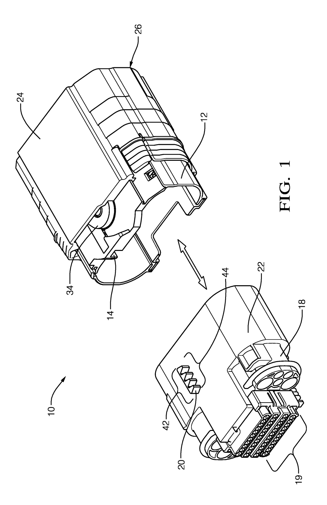
[0026]FIG. 1 illustrates a non-limiting example of a connector 10, that includes a first-housing 12 defining a guide-slot 14. The first-housing 12 may have multiple electrical terminals 16 (not shown) attached to a wire-bundle (not shown) that is a component of a wire-harness or other electrical-components. The first-housing 12 may also include wire seals and strain relief for the wires (not shown).

[0027]The connector 10 also includes a second-housing 18 configured to mate with the first-housing 12. The second-housing 18 may also have multiple corresponding mating electrical terminals 19 configured to mate with the electrical terminals 16 of the first-housing 12 attached to a wire-bundle that is a component of a wire-harness or other electrical-components (not shown). The second-housing 18 may also include wire seals and strain relief for the wires, and a perimeter seal (not shown) to form a seal with the first-housing 12. The second-housing 18 includes a linear-gear-rack 20 extendi...


PUM


Abstract

A connector includes a first-housing, a second-housing, a shroud, and a stacked-gear. The stacked-gear is moveably mounted to the first-housing. The stacked-gear engages a first-gear-rack on the second-housing and a second-gear-rack on the shroud. The second-housing is mated with the first-housing when the shroud is moved along a mating-axis of the connector. The stacked-gear engages at least two teeth on the first-gear-rack and on the second-gear-rack when the second-housing is mated with the first-housing. A rotation of the stacked-gear is greater than ninety degrees when the shroud is moved from an unmated-position to a mated-position. The stacked-gear initially engages a first-side of a first-tooth of the first-gear-rack when the first-housing receives the second-housing. A uniform mating-force is maintained as the shroud is moved from an unmated-position to a mated-position. A mechanical advantage to produce the mating-force is increased as the shroud is moved from an unmated-position to a mated-position.

Description

TECHNICAL FIELD OF INVENTION[0001]This disclosure generally relates to a connector, and more particularly relates to an electrical connector assembly with a mate-assist device.BACKGROUND OF INVENTION[0002]It is known to use mate-assist features on electrical connectors used in automotive applications, especially where a higher number of input / output (I / O) connections per system are required due to increased electrical content on the vehicle. Connectors utilizing an integral lever mechanism typically require pre-positioning of the connector prior to closing the lever assist mechanism. This multi-step mating process is cumbersome for assemblers, as these connection systems are not ergonomically friendly and are also prone to mating damage and / or mis-mating. Additionally, because these systems require tools and / or lever motion during mating, additional application package space is required reducing the total number of terminals possible in the connector.[0003]The subject matter discuss...

Claims


Application Information

Patent Timeline
Patent Type & Authority Patents(United States)
IPC IPC(8): H01R13/62H01R13/514H01R13/629
CPCH01R13/514H01R13/62944H01R13/62905H01R13/62938H01R13/62977
Inventor CAMPBELL, JEFFREY SCOTTWEBER, JR., WESLEY W.
Owner APTIV TECH LTD
Why Eureka
Try Eureka