Stamping machine

a stamping machine and stamping technology, applied in forging presses, forging/pressing/hammering apparatuses, shaping tools, etc., can solve the problems of inability to attach a diamond tip to the needle, inability to raise the stamping speed above 100 hz, and inability to solve solutions. , to achieve the effect of high speed

Active Publication Date: 2008-12-23
ROLAND DG CORP
View PDF8 Cites 20 Cited by
  • Summary
  • Abstract
  • Description
  • Claims
  • Application Information

AI Technical Summary

Problems solved by technology

However, because of problems due to needle weight and stamping mechanism weight, it is impossible to raise the stamping speed above 100 Hz.
However, these solutions are not desirable because attaching a diamond tip to the needle becomes impossible if the needle's size is greatly reduced.

Method used


Image

  • Stamping machine
  • Stamping machine
  • Stamping machine

Examples


Embodiment Construction

[0029]The present invention relates to pressing a working tool on a surface of an item and forming an image on the item at a high speed.

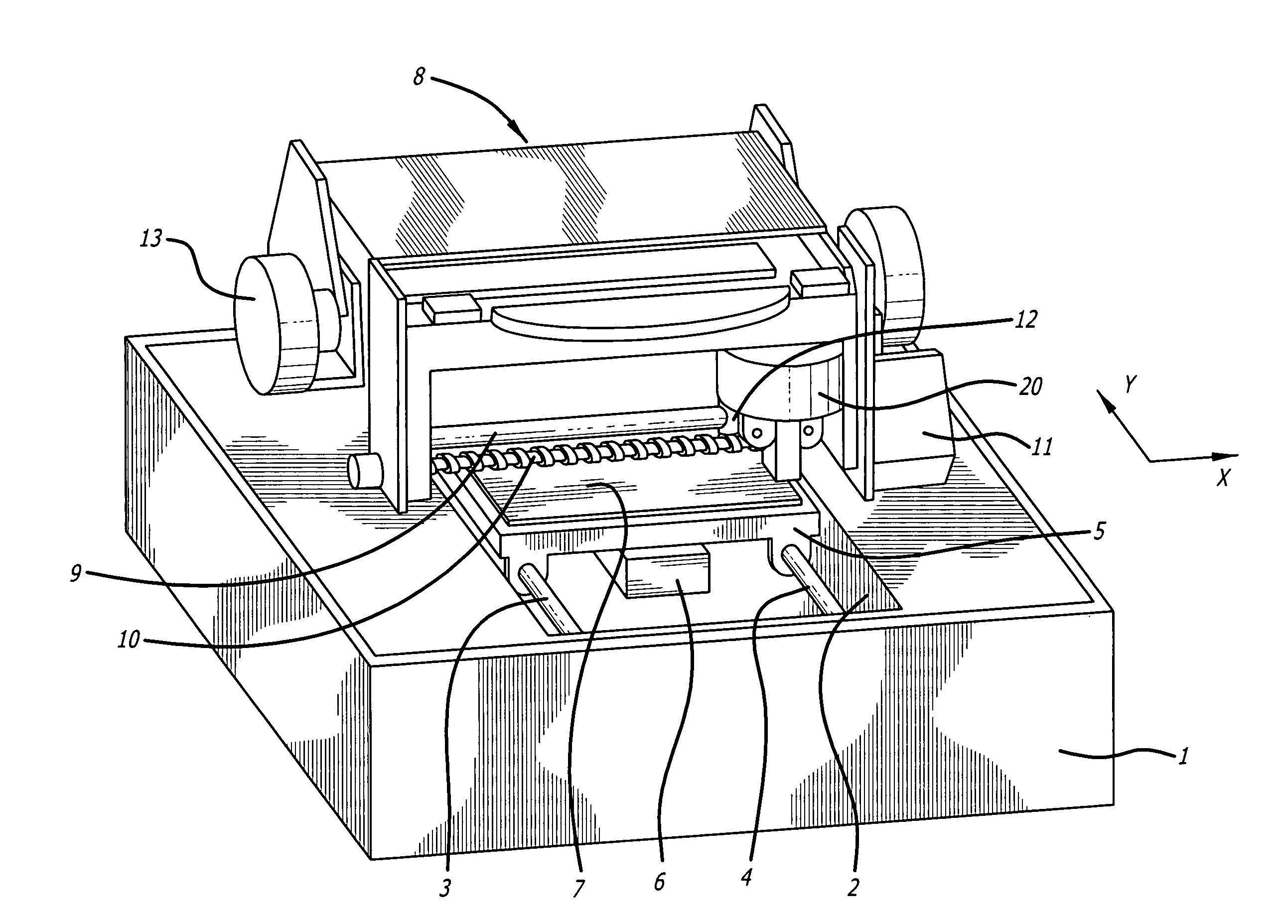
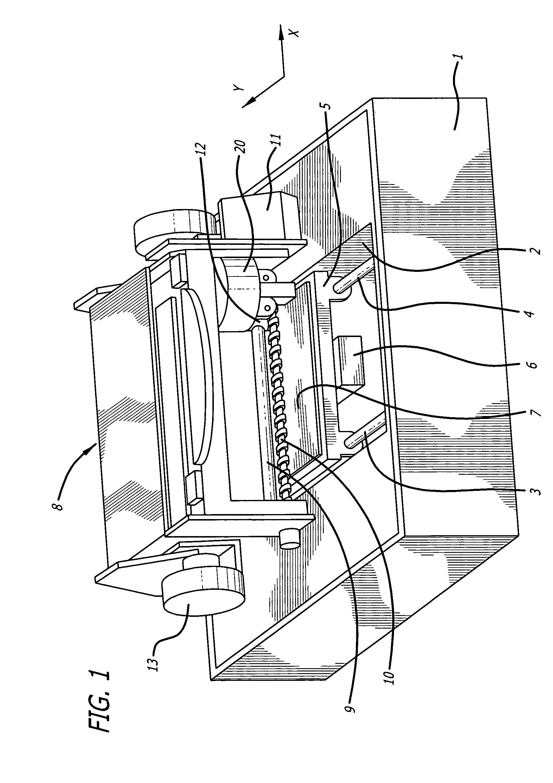
[0030]FIG. 1 is an exterior perspective view of a stamping machine in accordance with one embodiment of the present invention.

[0031]As shown in FIG. 1, the stamping machine comprises a case 1 preferably formed in a box-like shape having a space therein. An opening 2 is formed in a central part of the case 1. Guide shafts 3, 4 are formed in the interior of the case 1 at the opening 2. Preferably, the guide shafts 3, 4 extend in the Y-direction of FIG. 1 and are provided parallel to each other separated by a prescribed interval. A motor 6 for controlling movement in the Y-axis is provided in the interior of the case 1 at the opening 2 in order to move a pedestal 5 in the Y-direction along the guide shafts 3, 4.

[0032]When in use, an item to be worked (worked item) 7 is placed and held on the pedestal 5. The worked item 7 may be fixed to the pedestal 5 ...


PUM

PropertyMeasurementUnit
angleaaaaaaaaaa
diameteraaaaaaaaaa
diameteraaaaaaaaaa

Abstract

The present invention is related to a stamping machine for stamping an item at a high speed. The stamping machine comprises a case having an opening, at least one guide shaft formed in an interior of the case and extending in a first direction, a pedestal movable along the at least one guide shaft in the first direction for holding the worked item, and a stamping part for pressing the working tool against the worked item held on the pedestal. The stamping part comprises at least one guide shaft formed in an interior of the stamping part and extending in a second direction, a head driver formed in the interior of the stamping part and extending in the second direction, and a stamping head movable along the at least one guide shaft and the head driver in the second direction, wherein the stamping head is proximal to the pedestal.

Description

CROSS-REFERENCE TO RELATED APPLICATIONS[0001]Pursuant to 35 U.S.C. § 119(a), this application claims the benefit of earlier filing date and right of priority to Japanese Application No. 2005-195445, filed on Jul. 4, 2005, the contents of which is hereby incorporated by reference herein in its entirety.FIELD OF THE INVENTION[0002]The present invention relates to a stamping machine and, particularly, to a stamping machine for pressing a working tool on a surface of an item and capable of forming an image on the item at a high speed.BACKGROUND OF THE INVENTION[0003]A stamping machine is an apparatus for performing work on items such as accessories and jewelry. A prior art stamping machine is provided with a plunger so as to pass through a solenoid, and a working tool on a lower part of the plunger. One example of a working tool may be one with a diamond tip, the front end of which has been worked to 90 degrees and attached to a tip of a needle with a diameter of 2 mm. By passing electr...

Claims


Application Information

Patent Timeline
Patent Type & Authority Patents(United States)
IPC IPC(8): B21J11/00B21D5/06
CPCB44B3/005Y10S72/707
Inventor KUNO, TSUTOMUSHIKANO, YOSHIHIRO
Owner ROLAND DG CORP
Why Eureka
Try Eureka