One hand tourniquet with locking mechanism

a technology of locking mechanism and tourniquet, which is applied in the direction of fastening devices, snap fasteners, buckles, etc., can solve the problems affecting the safety of the member, and causing significant blood loss and renewed bleeding, etc., to achieve the effect of preventing the movement of the members

Inactive Publication Date: 2008-12-23
BIOTRACK +1
View PDF10 Cites 20 Cited by
  • Summary
  • Abstract
  • Description
  • Claims
  • Application Information

AI Technical Summary

Problems solved by technology

It is important for tourniquets to maintain tension reliably; a sudden accidental release of tourniquet tension can result in significant loss of blood and renewed bleeding.
Additionally, a person applying a tourniquet to himself typically will not have favorable leverage to apply force.
The tourniquet of Mayo et al. does not provide a mechanism for locking tourniquet tension so that the tourniquet cannot be accidentally released.
Mayo et al. has release mechanisms that can be easily triggered accidentally, resulting in sudden and complete loss of tourniquet tension.
This is dangerous to injury victims, because sudden loss of the tourniquet can result in significant additional loss of blood.

Method used


Image

  • One hand tourniquet with locking mechanism
  • One hand tourniquet with locking mechanism
  • One hand tourniquet with locking mechanism

Examples


Embodiment Construction

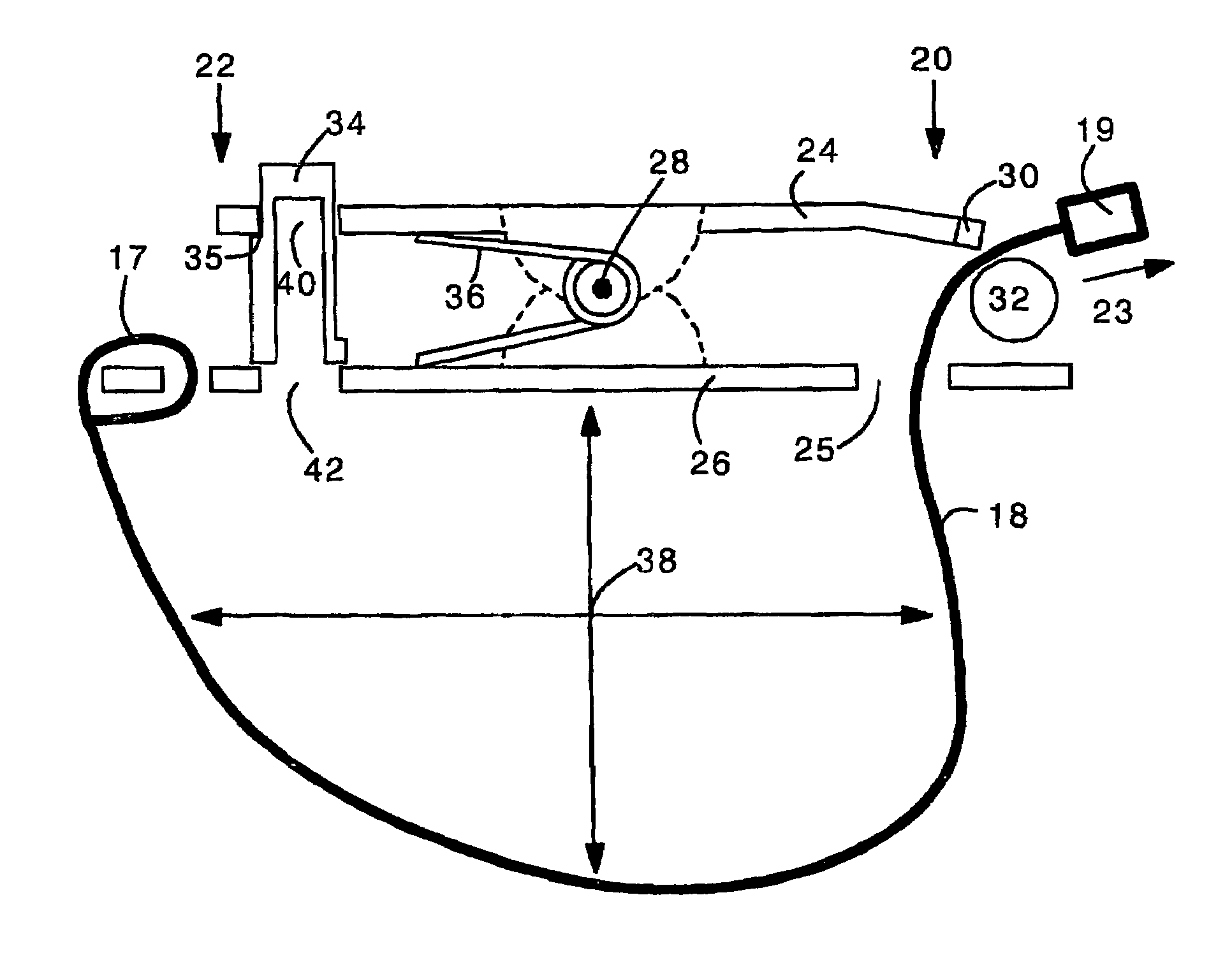
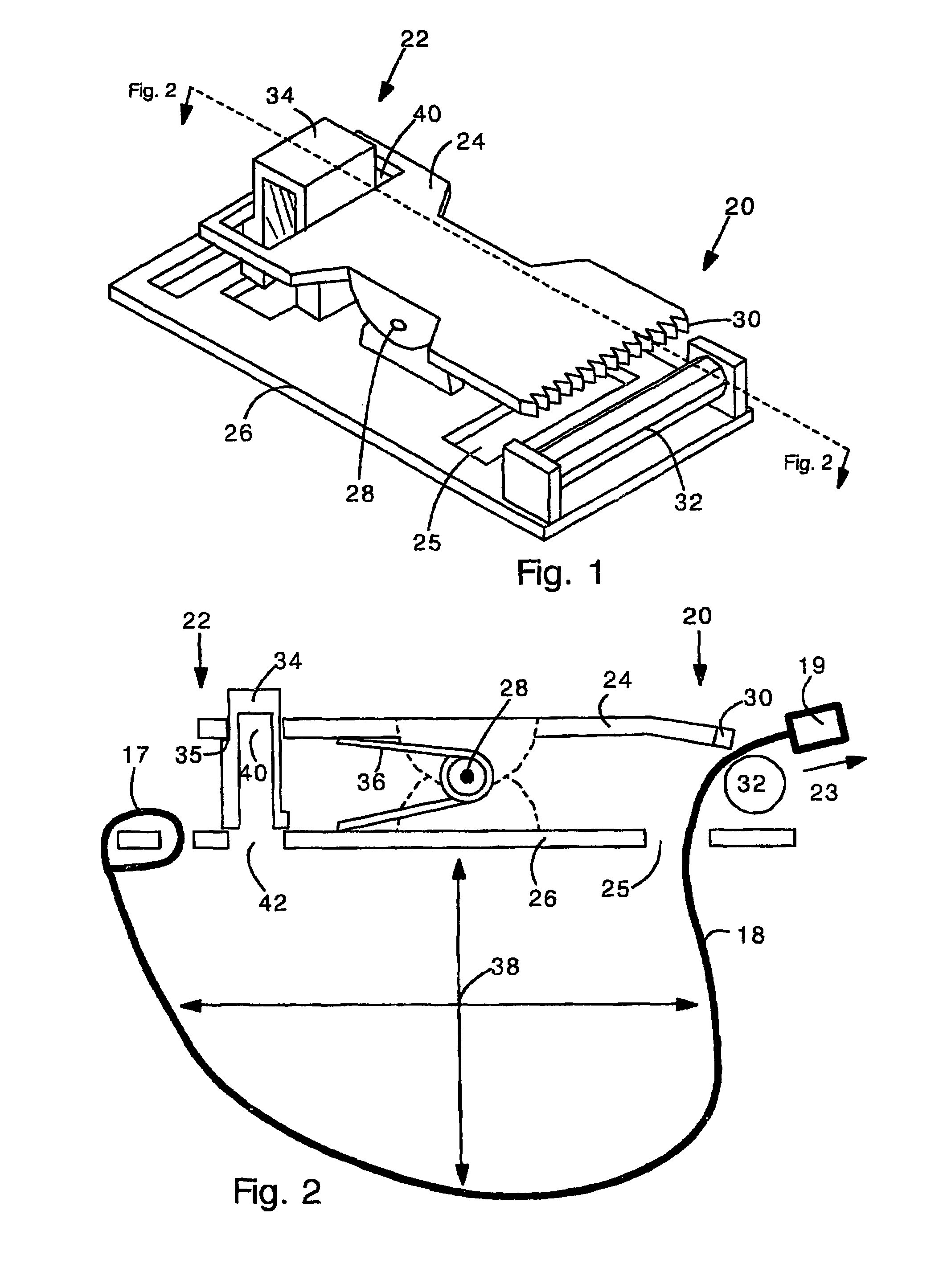
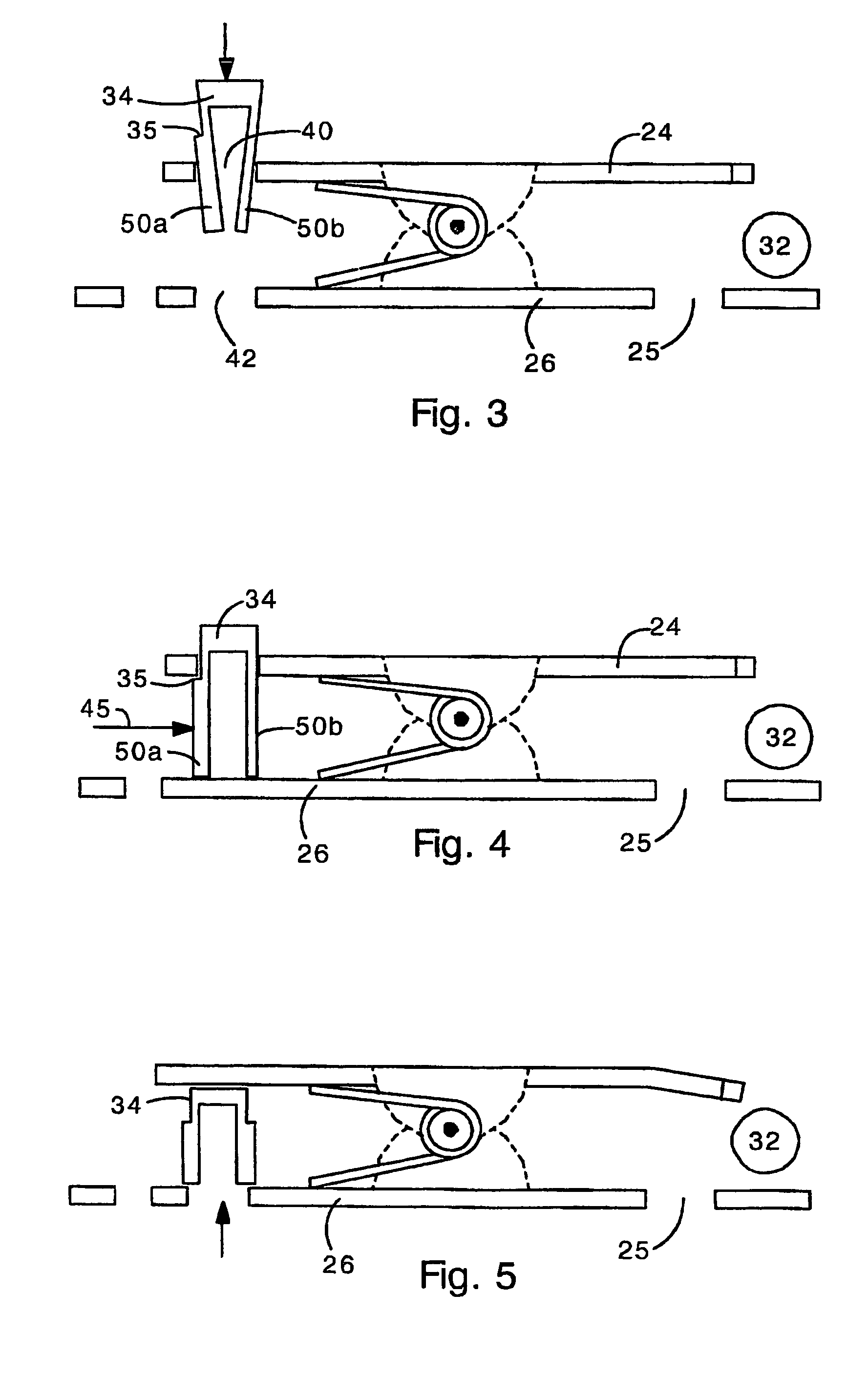
[0020]The present invention provides a tourniquet that can be applied with one hand and requires only a small amount of force to completely stop blood flow. The present tourniquet comprises a pair of plates that are pivotally connected and biased together on a front end to form a clamp. The clamp allows elastomeric cord material to be pulled from the tourniquet such that the tourniquet is tightened. The tourniquet also includes a safety lock for preventing the plates from moving after the tourniquet has been set. Preferably, the safety lock comprises a button that jams the plates apart on a back side, thereby preventing the plates from moving apart on the front side. Additionally, the tourniquet may include a dual-sided press connector (e.g. similar to well known connectors sold under the trademarked names FASTEX™ or SIDE SQUEEZE™) for allowing rapid but accident-resistant release of the tourniquet.

[0021]FIG. 1 shows a perspective view of the tourniquet clamp of the present inventio...


PUM


Abstract

Provided is a tourniquet having two opposing and pivotally movable plates. The plates comprise a clamp that pinches an elastomeric cord. The plates are pivotally biased together by a spring. The cord is attached to a back end of the clamp. A free end of the cord is squeezed by the plates such that a loop of cord is provided. The cord can be pulled from the clamp to reduce the size of the loop. The clamp comprises a safety lock that prevents movement of the plates and slipping of the cord. The safety lock can comprise a button disposed between the plates in the back end of the clamp, preventing the plates from moving together in the back portion, and therefore from moving apart in a front portion that grips the cord. Also, the tourniquet clamp can comprise a dual-sided press connector mechanism for fast release of tourniquet tension.

Description

RELATED APPLICATIONS[0001]The present application claims the benefit of priority from provisional application 60 / 591,947, filed on Jul. 29, 2004.GOVERNMENT INTEREST[0002]The development of the present invention was supported by the US Government under contract number OST 02-DH-08 from the US Special Forces. The Government has certain rights in the invention.FIELD OF THE INVENTION[0003]The present invention relates generally to tourniquet devices for blocking blood flow to an injured limb. More particularly, the present invention relates to a tourniquet device that can be applied, adjusted, and released with one hand.BACKGROUND OF THE INVENTION[0004]Tourniquet devices are commonly used in emergency medicine to stop blood flow to and bleeding from an injured limb. Tourniquets employ a length of cordage tightened around a limb to stop blood flow and allow clotting to occur. After a tourniquet is applied long enough to allow blood clotting or to stabilize the injury, in some cases the t...

Claims


Application Information

Patent Timeline
Patent Type & Authority Patents(United States)
IPC IPC(8): A61B17/00A44B1/04F16G11/10F16G3/02F16G3/00F16G11/00A44B11/25A44B17/00
CPCA61B17/132A61B17/1322A61B17/1327Y10T24/44427Y10T24/3423Y10T24/4016
Inventor LICATA, MARKWARD, KEVIN R.CARR, JR., MARCUS E.
Owner BIOTRACK
Why Eureka
Try Eureka