Drainage device for arrangement on a floor tile having a drain water aperture and arrangement of such a drainage device on a floor tile

a drainage device and drainage device technology, which is applied in the direction of sewerage structures, cleaning equipments, applications, etc., can solve the problems of difficult placement of natural stone tiles in the corner of a room, stone tiles with a slope towards the central aperture,

Inactive Publication Date: 2009-01-06
DALLMER GMBH & CO KG
View PDF16 Cites 25 Cited by
  • Summary
  • Abstract
  • Description
  • Claims
  • Application Information

AI Technical Summary

Benefits of technology

[0018]In particular, one of the two seals may rest on the upper side of the flange of the outer pipe length or the outer tubular section and the other of the two seals may bear on the underside of the bend, which extends at least partially above the flange of the inner pipe length or the inner tubular section. The double bend therefore means that the flange of the inner pipe length or the inner tubular section can extend between two seals, which simultaneously bear against the flange of the outer pipe length or the outer tubular section and against the bend thereof. In this way the two flanges are readily sealed against one another whilst at the same time ensuring the mobility of the flanges relative to one another.
[0023]At the same time, sealing devices, in particular a sealing ring or a lip packing, which allow a movement of the union connections relative to one another, may furthermore be arranged between the two union connections. The union connections, moveably arranged one inside the other by way of the sealing devices, readily permit movement of the drain well in relation to the seating devices. For example, the radially outer edge of the inner union connection may be separated at a distance from the radially inner edge of the outer union connection, in order to facilitate movement of the union connections relative to one another. The sealing devices can furthermore feasibly be radially widened in such a way as to facilitate movement of the union connections.

Problems solved by technology

Such natural stone tiles, which have a slope towards the central aperture, for example, can be very heavy and unwieldy.
It may be difficult to place such a natural stone tile in the corner of a room, for example in a shower tray.

Method used


Image

  • Drainage device for arrangement on a floor tile having a drain water aperture and arrangement of such a drainage device on a floor tile
  • Drainage device for arrangement on a floor tile having a drain water aperture and arrangement of such a drainage device on a floor tile
  • Drainage device for arrangement on a floor tile having a drain water aperture and arrangement of such a drainage device on a floor tile

Examples


Embodiment Construction

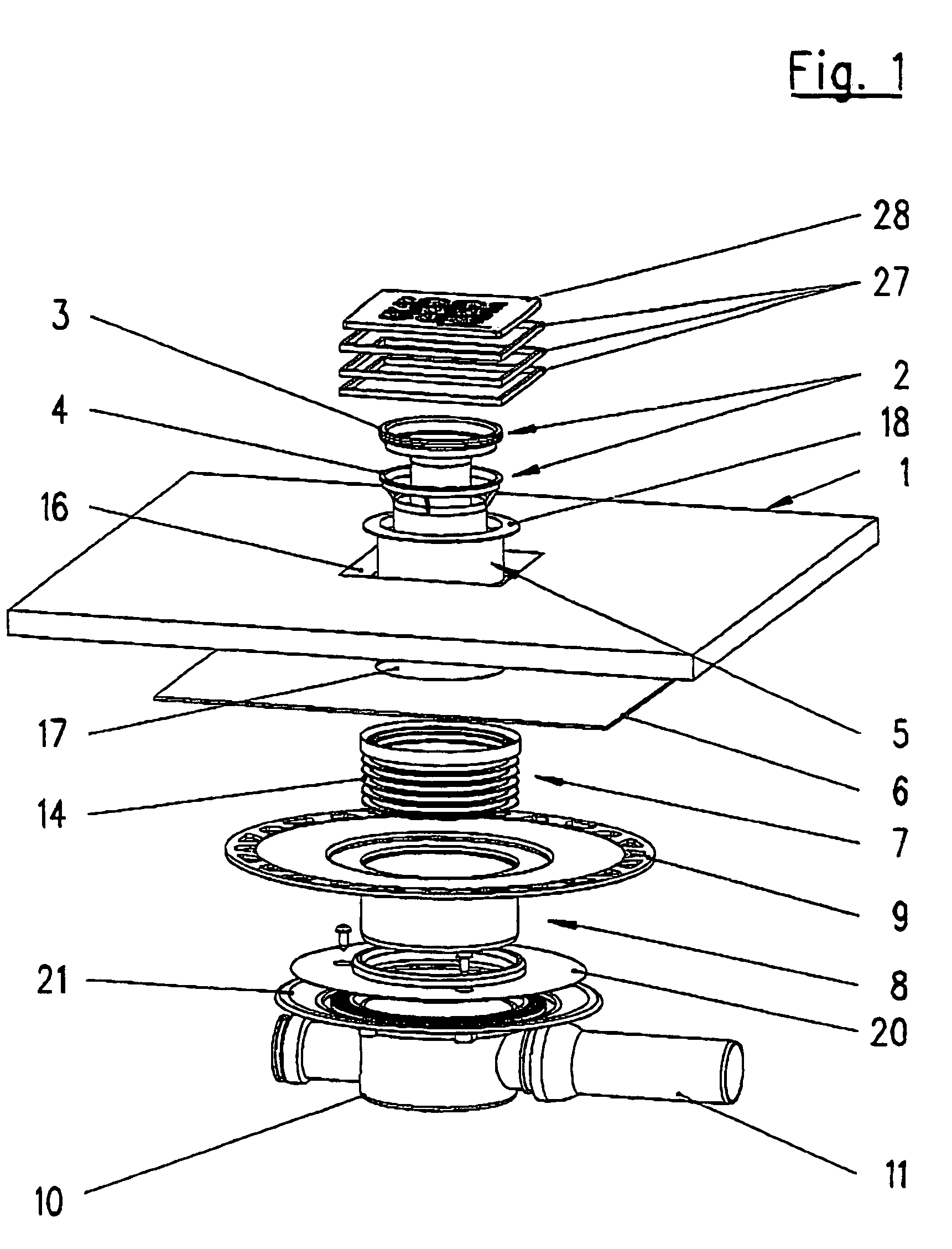
[0043]The arrangement shown in FIG. 1 is made up of a floor tile 1 and a drainage device. The drainage device includes an odor trap unit 2 having an inner part 3 and an outer part 4, a first fixing part 5, a sheet metal plate 6, a second fixing part 7, a pipe length 8 having a flange 9, and a drain well 10. In the exemplary embodiment shown the drain well 10 is connected to a drainage pipe 11, which extends horizontally to the side.

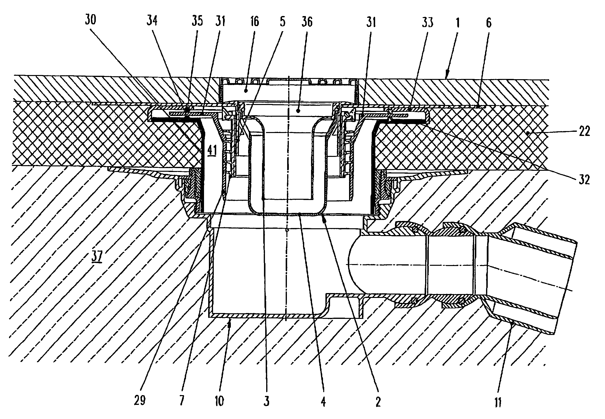
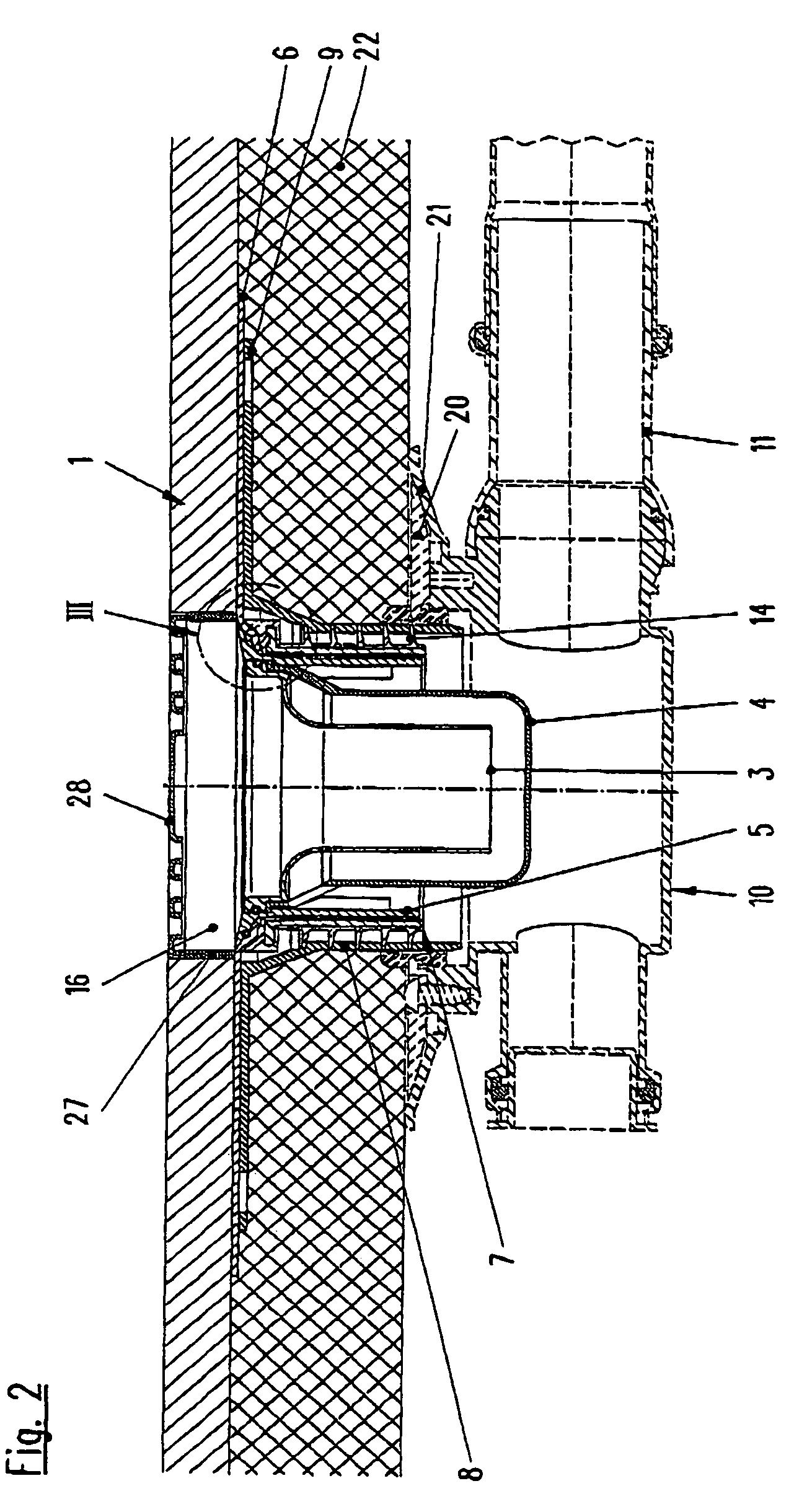
[0044]It can be seen from the sectional view in FIG. 2, in particular, that the odor trap unit 2 is of conventional siphonic construction. The inner part 3 extends in the form of a pipe union connection, open at the bottom, into the outer part 4, which is closed off at the bottom like a well, and has an overflow at the top.

[0045]It can also be seen from FIG. 2 and FIG. 3 that the first fixing part 5 has an external thread 12 on its outside, whereas the second fixing part 7 has an internal thread 13 on its inside. In FIG. 2 and FIG. 3 the internal thread 1...


PUM


Abstract

Drainage device for arrangement on a floor tile, the drainage device, when at least partially assembled in the floor, has at least two pipe lengths moveable relative to one another in such a way that a movement of the pipe lengths relative to one another allows an aperture in the floor tile and the upper inlet aperture of the drainage device to be made to coincide at least partially with one another. At the same time the pipe lengths have flanges extending radially outwards, which are sealed against one another by seals.

Description

BACKGROUND OF THE INVENTION[0001]The present invention relates to a drainage device for arrangement on a floor tile having a drain water aperture according to the preamble of claim 1 and to an arrangement of such a drainage device on a floor tile.[0002]Fitting drainage devices to floor tiles, which may be composed of natural stone, for example, is already known. Such natural stone tiles, which have a slope towards the central aperture, for example, can be very heavy and unwieldy. It may be difficult to place such a natural stone tile in the corner of a room, for example in a shower tray. This is the case particularly when the upper inlet aperture of the drainage device, already partially preinstalled in the floor, does not align with the aperture in the natural stone tile.[0003]It is an object of the present invention to create a drainage device of the aforementioned type, which will facilitate assembly of the drainage device together with a floor tile.SUMMARY OF THE INVENTION[0004]...

Claims


Application Information

Patent Timeline
Patent Type & Authority Patents(United States)
IPC IPC(8): A47L3/00F16L5/00
CPCE03F5/0408E03F5/0409E03F2005/0413E03F2005/0415E03F2005/0416Y10T137/6988
Inventor DALLMER, JOHANNES
Owner DALLMER GMBH & CO KG
Why Eureka
Try Eureka