Connector cover

a technology of connectors and cover shells, applied in the direction of live contact access prevention, coupling device connection, electrical apparatus, etc., can solve the problems of affecting the appearance of the external appearance of the cover shell, affecting the safety of the connector, and the two cover shells are likely to be separated, so as to improve the external appearance, prevent the inadvertent disengagement of the lock piece, and improve the effect of external appearan

Active Publication Date: 2009-01-13
SUMITOMO WIRING SYST LTD
View PDF3 Cites 33 Cited by
  • Summary
  • Abstract
  • Description
  • Claims
  • Application Information

AI Technical Summary

Benefits of technology

[0010]The lock-piece protector preferably is present at a position substantially diagonally opposite to the leading end corner of the lock piece. With such an arrangement, the interference of the wires and the like with the leading end corner of the lock piece can be prevented effectively.
[0021]The lock piece preferably includes a reinforcement insertable between adjacent locks. Thus, the lock piece is stronger, more springy and less likely to be damaged.

Problems solved by technology

At that time, members such as wires and external matter may interfere with the connector.
Particularly, there has been a problem that the two cover shells are likely to be separated if the lock piece near the tube holding portion holding the corrugated tube gets caught by a wire or the like, the frequent action of external forces on the corrugated tube being a contributing negative factor.

Method used


Image

  • Connector cover
  • Connector cover
  • Connector cover

Examples


first embodiment

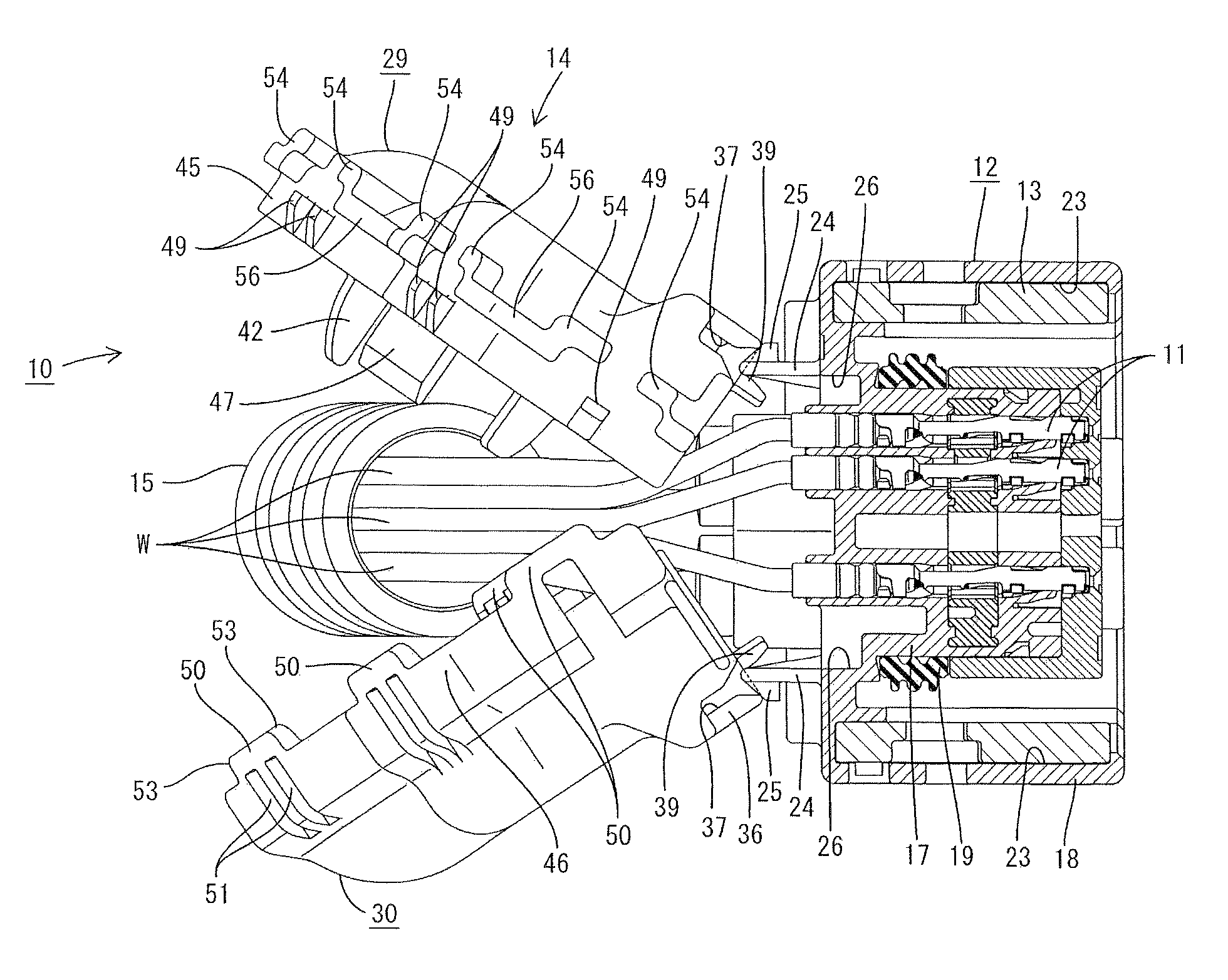
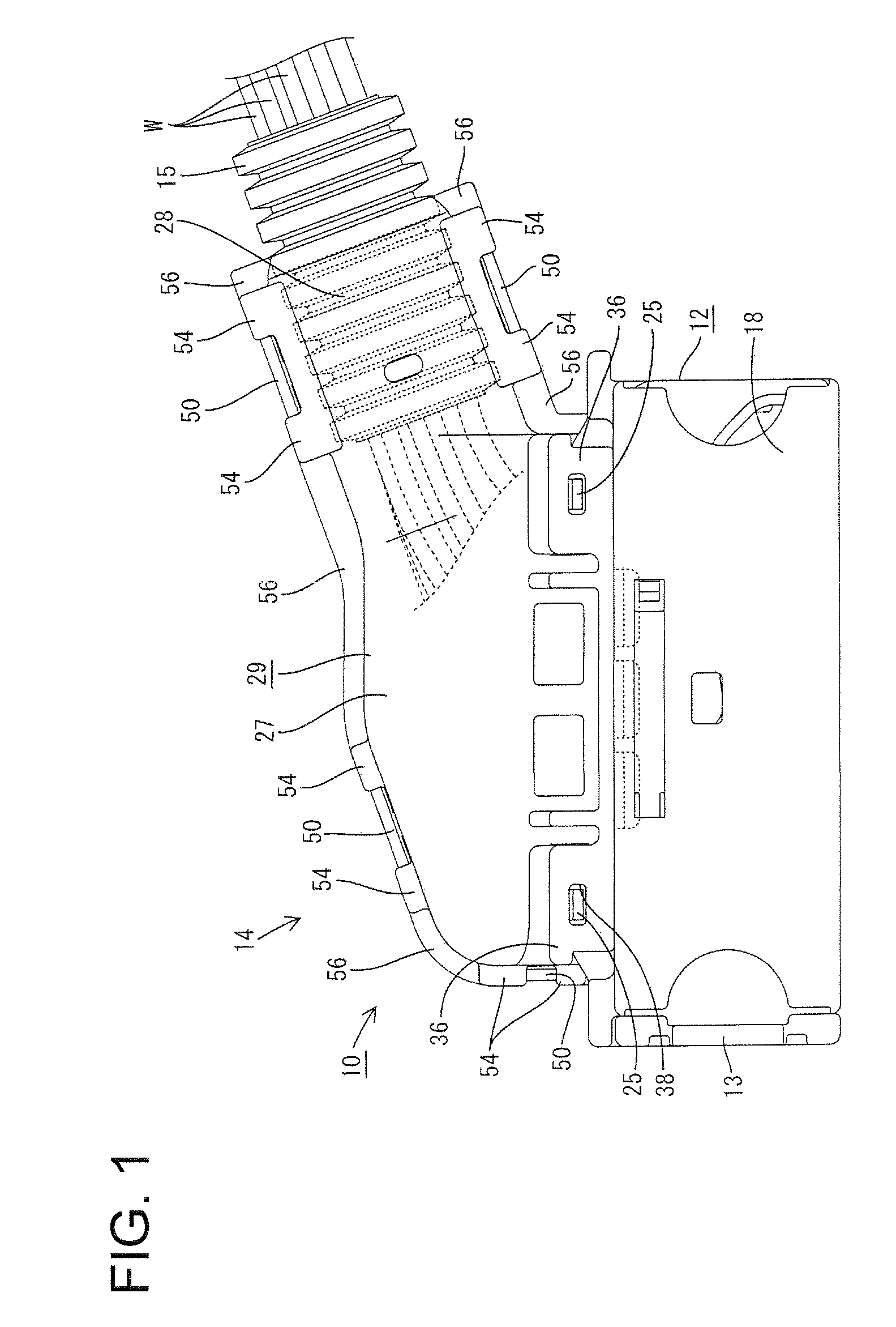
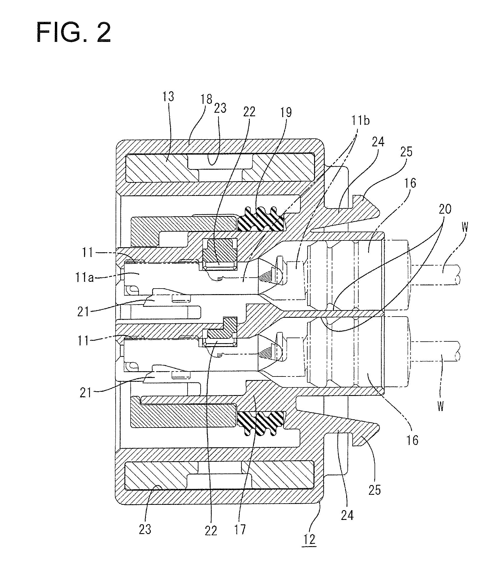
[0052]A watertight connector in accordance with the invention is described with reference to FIGS. 1 to 23 and is identified generally by the numeral 10. In the following description, reference is made to FIGS. 2 and 5 concerning the vertical direction (longitudinal direction) and to FIGS. 1, 6 and 8 concerning left and right sides. A connection side (lower side in FIG. 1) with a mating connector and an opposite side (upper side in FIG. 1) are referred to respectively as front and rear ends.

[0053]As shown in FIG. 2, the connector has a plurality of terminal fittings 11 to be connected with ends of wires W and accommodated in a housing 12 for at least partly accommodating the terminal fittings 11. As shown in FIG. 1, a slide lever 13 is mounted laterally to the housing 12 and a cover 14 is mounted on the rear end of the housing 12 to hold a corrugated tube 15.

[0054]The corrugated tube 15 is made e.g. of synthetic resin and defines a flexible bellows with alternating projections and r...

second embodiment

[0111]Although the reverse tapered surfaces preferably are formed in the substantially entire overlapping-wall protectors in the second embodiment, they may be formed in parts of the overlapping-wall protectors according to the invention. In such a case, a pair of reverse tapered surfaces may be arranged at the substantially opposite sides or only at one side of each lock piece. Further, the tapered surfaces of the second overlapping walls may be partly or entirely omitted.

[0112]Although the wider lock pieces and the narrower lock piece are provided and each wider lock piece is engaged with two locks in the above embodiments, one wider lock may be engaged with each wider lock piece. Connector covers including only narrower lock pieces and connector covers including only wider lock pieces each engageable with two locks also are embraced by the present invention. Further, three or more lock pieces may be engaged with each wider lock. Furthermore, the reinforcing portion may be omitted...


PUM


Abstract

A connector cover (14) holds a corrugated tube (15) surrounding wires (W) drawn out from the rear side of a housing (12) and is mounted on the rear side of the housing (12). The cover (14) has first and second cover shells (29, 30) to be assembled with each other. The cover shells (29, 30) include tube holders (28) capable of holding an end portion of the corrugated tube (15) therebetween. The first cover shell (29) includes locks (49), and the second cover shell (30) includes lock pieces (50) engageable with the locks (49). The first cover shell (29) has lock-piece protecting portions (54) to be arranged adjacent to leading end corners (53) of the lock pieces (50) corresponding to the tube holder (28) and projecting more outward than the lock pieces (50) in the thickness directions thereof.

Description

BACKGROUND OF THE INVENTION[0001]1. Field of the Invention[0002]The invention relates to a connector cover.[0003]2. Description of the Related Art[0004]Many connectors are mounted at an end of an automotive wiring harness, and some of these connectors are provided with a connector cover for holding a corrugate tube for protecting wires. An example of such a connector is disclosed in U.S. Pat. No. 7,201,592. This connector is provided with a housing for accommodating terminal fittings connected with ends of wires, a corrugated tube for protecting the wires drawn out from the rear side of the housing by surrounding them, and a connector cover adapted to hold an end portion of the corrugated tube and mountable on the rear side of the housing. The connector cover is comprised of a pair of cover shells to be assembled with each other, and each of the both cover shells includes a tube holding portion for holding the corrugated tube and a housing mounting portion to be mounted on the housi...

Claims


Application Information

Patent Timeline
Patent Type & Authority Patents(United States)
IPC IPC(8): H01R13/58
CPCH01R13/4223H01R13/4361H01R13/506H01R13/5205H01R13/5219H01R13/562H01R13/567H01R13/5825H01R13/6273Y10S439/906
Inventor TSUJI, TAKESHI
Owner SUMITOMO WIRING SYST LTD
Why Eureka
Try Eureka