Keyed system for connection of filter cartridge to filter holder

a technology of filter cartridges and keyed systems, applied in the direction of cartridge filters, filtration separation, separation processes, etc., can solve the problem that the filter cartridge cannot be installed on any other than its own matching holder, and achieve the effect of reducing the incentive to provide cheap, reducing the cost of low-quality copies, and controlling the product lines

Inactive Publication Date: 2009-01-13
OMNIPURE FILTER CO INC
View PDF43 Cites 32 Cited by
  • Summary
  • Abstract
  • Description
  • Claims
  • Application Information

AI Technical Summary

Benefits of technology

[0007]Also, a filter manufacturer may control his product lines more carefully by using the invented key system. A manufacturer may key his holders and filter cartridges differently for different countries, different clients, different distributors, or for different time periods. This technique may be used to prevent unauthorized or low-quality copies of the manufacturer's filter cartridges from easily being made. With so many differently-keyed cartridges in the marketplace provided by the original manufacturer, the incentive to provide cheap, low quality copies will be minimized, due to the expense of retooling for each “key and lock” set.

Problems solved by technology

This way, a filter cartridge from one set may not be mixed with a cartridge from another set, and, therefore, a filter cartridge may not be installed on any but its own matching holder.
This system may include a plurality of sets of filters and holders, each set having a differently-located key and lock, wherein the key and lock of each set cooperate with each other to allow that filter to be installed in that holder, but that filter may not be installed in any other holder because the key or lock of that filter does not cooperate with the key or lock of the other holder.

Method used


Image

  • Keyed system for connection of filter cartridge to filter holder
  • Keyed system for connection of filter cartridge to filter holder
  • Keyed system for connection of filter cartridge to filter holder

Examples


Embodiment Construction

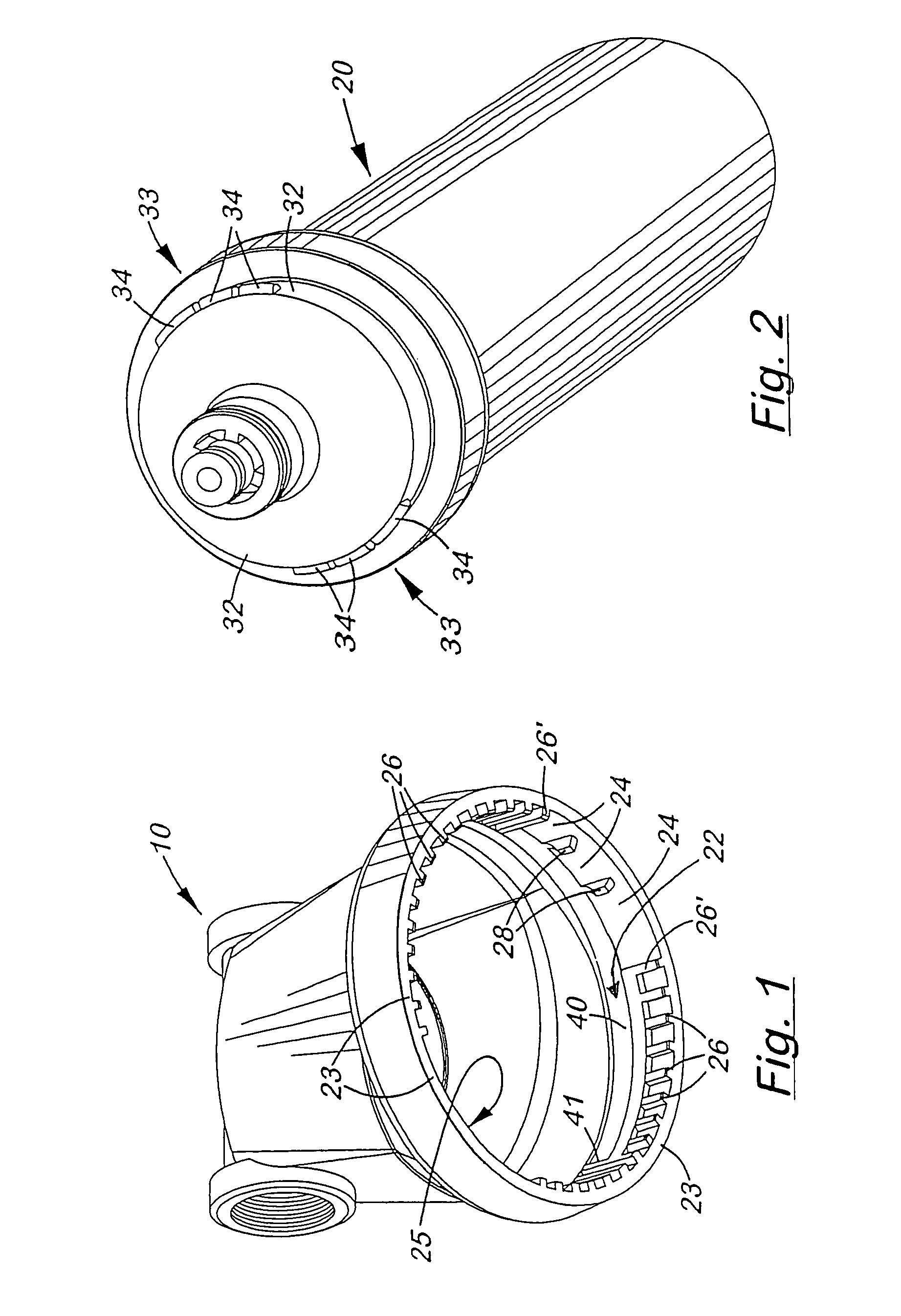
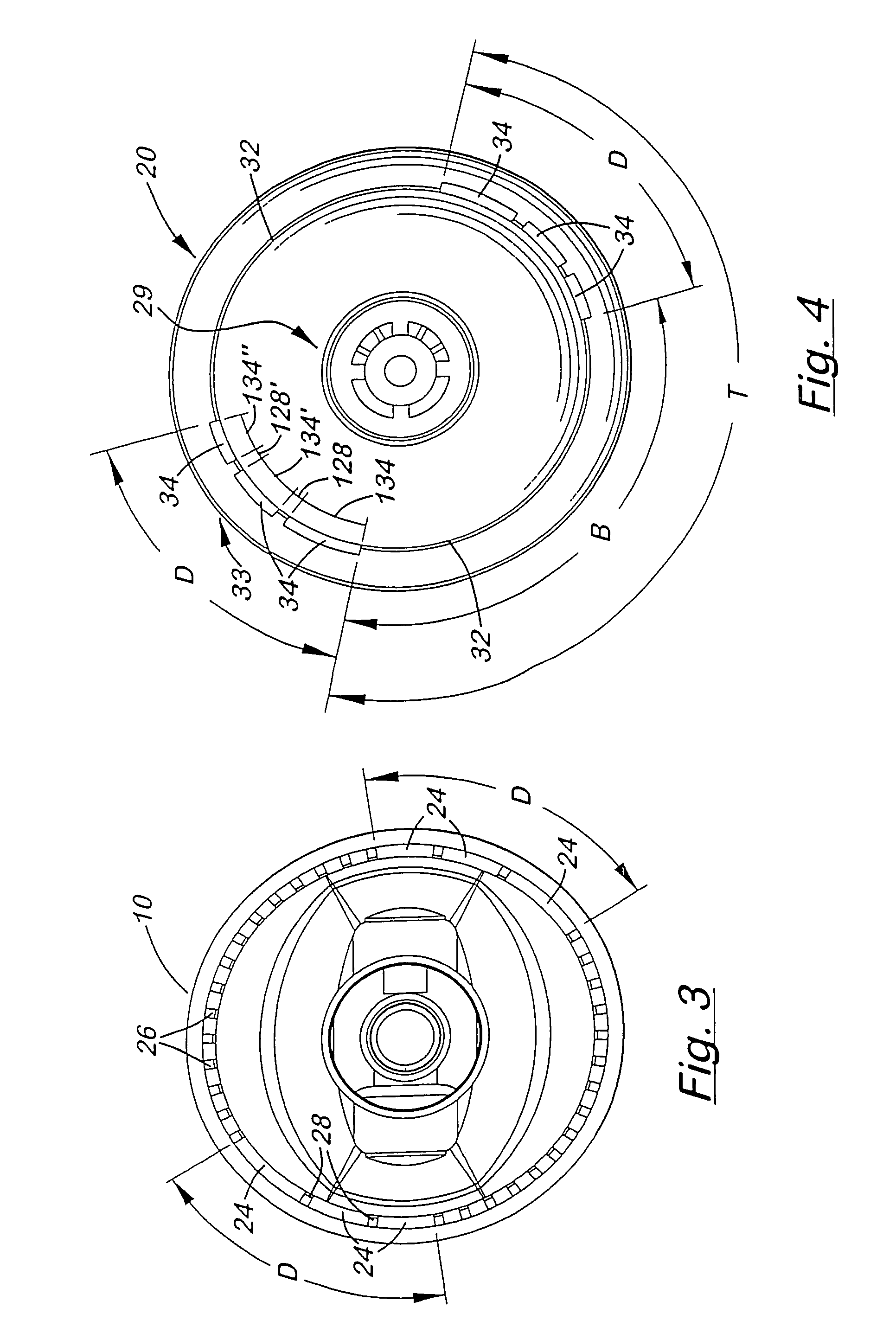
[0044]Referring to the Figures, there are shown several, but not the only embodiments of the invented key system. FIGS. 1-11 illustrate a filter cartridge keyed shoulder embodiment of the invented keyed system. FIGS. 12-22 illustrate a tubular connector embodiment of the invented keyed system.

[0045]The key system structures are located on surfaces of filter cartridges (or “filters”) and holders that contact each other during connection of the cartridge to the holder. This may be either surfaces that are involved in mainly providing a physical connection between the cartridge and holder or that also are involved in providing a fluid connection between the cartridge and the holder.

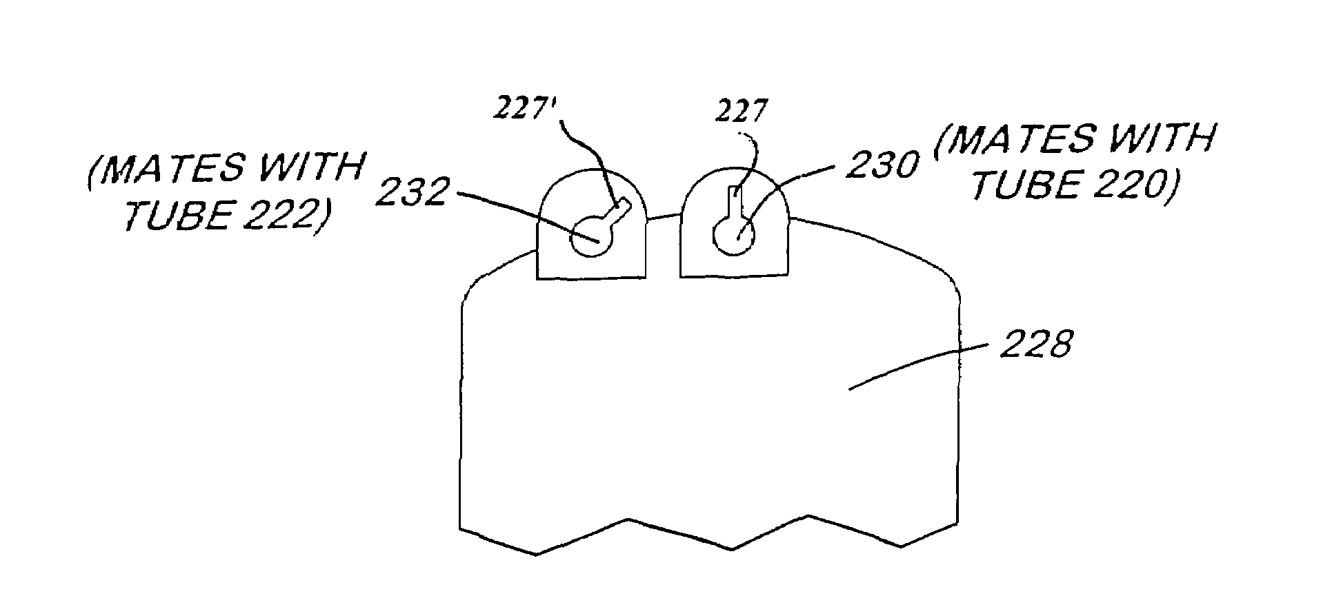
[0046]An example of key system structure on surfaces that are involved in providing physical connection, rather than fluid connection, is the key system structure on a shoulder of a filter cartridge that fits up into a valve-head holder. These areas are surfaces that do not normally liquid-seal to each other...


PUM

PropertyMeasurementUnit
angleaaaaaaaaaa
circumferenceaaaaaaaaaa
cooperating perimetersaaaaaaaaaa

Abstract

Embodiments of a key system for filters and their connecting heads, brackets, or other holders are shown. The filter cartridge and its holder each have a keyed surface, one being a protruding “key” and one being a recessed “lock”. Cooperation of these keyed surfaces is required in order for the filter cartridge to be installed in the holder, so that mis-matched cartridges cannot be installed into the holder, for example, to prevent a particular type of cartridge from being placed in a filtration or other process where it would be inappropriate, or undesired. The keyed surfaces are selectively locate-able preferably at different circumferential locations on a perimeter of the filter and a corresponding location on a perimeter of the head / holder. The perimeter may be, for example, on an outer shoulder surface of a filter and an inner surface of a valve head, or on outer and inner surfaces of connectors that provide a liquid seal between the filter and the head / holder.

Description

[0001]This application is a continuation-in-part of patent application Ser. No. 10 / 786,655, filed Feb. 24, 2004, and issued on Dec. 20, 2005 as U.S. Pat. No. 6,977,006, which is a continuation of patent application Ser. No. 09 / 928,666, filed Aug. 11, 2001, and issued on Feb. 24, 2004 as U.S. Pat. No. 6,695,891, which is a non-provisional application claiming priority of provisional patent application Ser. No. 60 / 224,632, filed Aug. 11, 2000, and also claims priority of prior, provisional patent application Ser. No. 60 / 272,221, filed Feb. 27, 2001, which are herein incorporated by this reference. This application also a continuation-in-part of, and claims priority of, patent application Ser. No. 11 / 200,864, filed on Aug. 9, 2005, and issued on 06 Feb. 2007 as U.S. Pat. No. 7,172,693, which is a continuation of patent application Ser. No. 10 / 372,040, filed Feb. 21, 2003, and issued as U.S. Pat. No. 6,926,826 on Aug. 9, 2005, which claims priority of provisional application 60 / 358,692,...

Claims


Application Information

Patent Timeline
Patent Type & Authority Patents(United States)
IPC IPC(8): B01D35/30B01D27/08
CPCB01D35/30B01D46/0004B01D46/009B01D46/2411B01D46/2414B01D35/306B01D2201/302B01D2201/4046B01D2265/026Y10S285/914
Inventor REID, ROGER P.
Owner OMNIPURE FILTER CO INC
Why Eureka
Try Eureka