Aerosol spray texture apparatus for a particulate containing material

a technology of texture and aerosol, which is applied in the direction of lighting and heating apparatus, combustion types, transportation and packaging, etc., can solve the problems of inoperable system, all of the acoustic texture material out of the aerosol container, and the inert gas escapes, so as to achieve more control over the amount of texture material dispensed

Inactive Publication Date: 2009-01-27
HOMAX PRODS
View PDF74 Cites 33 Cited by
  • Summary
  • Abstract
  • Description
  • Claims
  • Application Information

AI Technical Summary

Benefits of technology

[0027]The present invention comprises a container system for containing the texture material and a compressed inert gas as a propellant, a valve assembly operable in an open and close configuration for allowing or preventing fluid flow from the container assembly, an outlet assembly for dispersing the texture material dispensed thereby, and a metering assembly that interacts either with the valve assembly or the outlet assembly to allow the user to control the amount of texture material dispensed.
[0028]The metering system may be as simple as a collar that limits the outlet assembly to limit the flow rate of the texture material exiting the system and thus provide the user with more control over the amount of texture material dispensed.

Problems solved by technology

While commercially viable, the use of compressed inert gas to dispense acoustic texture material from an aerosol container assembly presents several problems.
First, if the aerosol system is operated while inverted, the compressed inert gas escapes and the system becomes inoperative.
Second, the compressed inert gas can force all of the acoustic texture material out of the aerosol container in a matter of seconds.
An inexperienced user can thus inadvertently and ineffectively empty the entire container of acoustic texture material.
The foam material does not contain particulate material, and thus the resulting texture formed does not match an existing coat of true acoustic texture material.
However, such prior art aerosol spray texture devices have not been properly adapted to deliver a texture having particulate matter therein to provide the rougher texture.

Method used


Image

  • Aerosol spray texture apparatus for a particulate containing material
  • Aerosol spray texture apparatus for a particulate containing material
  • Aerosol spray texture apparatus for a particulate containing material

Examples


first embodiment

III. First Embodiment

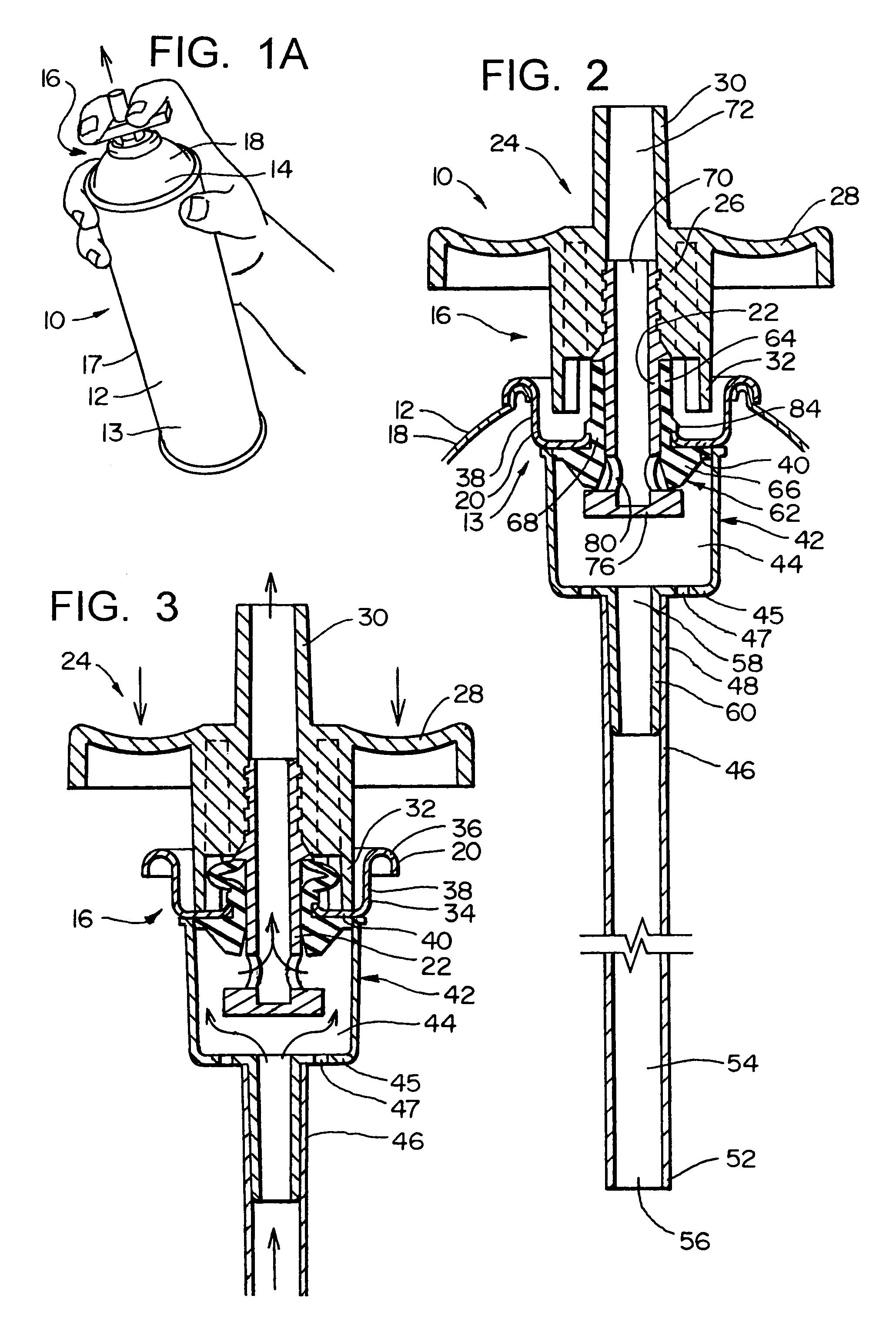
[0116]In FIG. 1A, it can be seen that the apparatus 10 of the present invention comprises an aerosol container 12 defining a main pressure chamber 13, and having at its upper end 14 a valve assembly 16. The container 12 has an overall cylindrical configuration, comprising a cylindrical sidewall 17, a top wall 18 (either integral with the sidewall 17 or made separately), and a bottom wall (not shown for ease of illustration). The valve assembly 16 is mounted at the center of the top wall 18.

[0117]The valve assembly 16 comprises a valve housing 20 mounted to the top container wall 18, and a valve stem or element 22 positioned within the housing 20 for movement between the closed position of FIG. 2 to the open position of FIG. 3. Fixedly attached to the upper end of the valve element 22 is a manually operable actuating and discharge portion 24, comprising a mounting portion 26, a cross bar 28, a discharge nozzle 30 extending upwardly from the mounting portion of 26...

second embodiment

IV. Second Embodiment

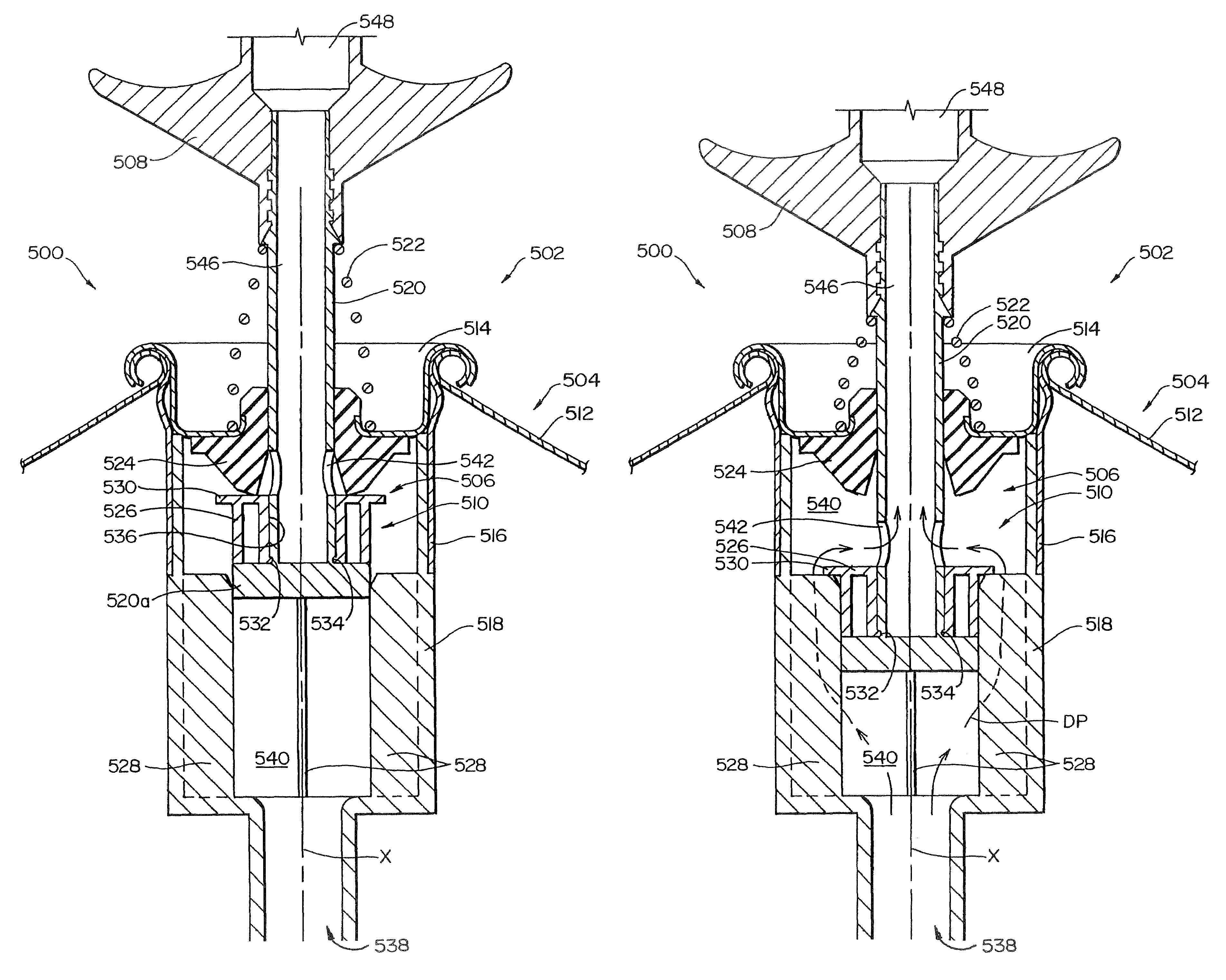
[0133]A second embodiment of the present invention is shown in FIG. 4. This is substantially the same as the first embodiment, except that the vent openings (designated 47a) are positioned in the sidewall of the housing 42a so that these direct flow laterally into the chamber 44a at the location of the intake openings 80a. It is surmised that this location of the vent openings 47a are able to be oriented to effect a tangential swirling pattern, or oriented more radially to provide a more direct force, in the vicinity of the openings 80a to enhance proper movement of the particles.

[0134]FIG. 5 is an enlarged view giving in inches the dimensions of a prototype built in accordance with the teachings of the present invention, and also to show the components more clearly. It is to be recognized, of course, that these dimensions could be increased or decreased within certain limits (e.g. ten percent, twenty percent, or possibly as high as fifty percent or higher, and ...

third embodiment

V. Third Embodiment

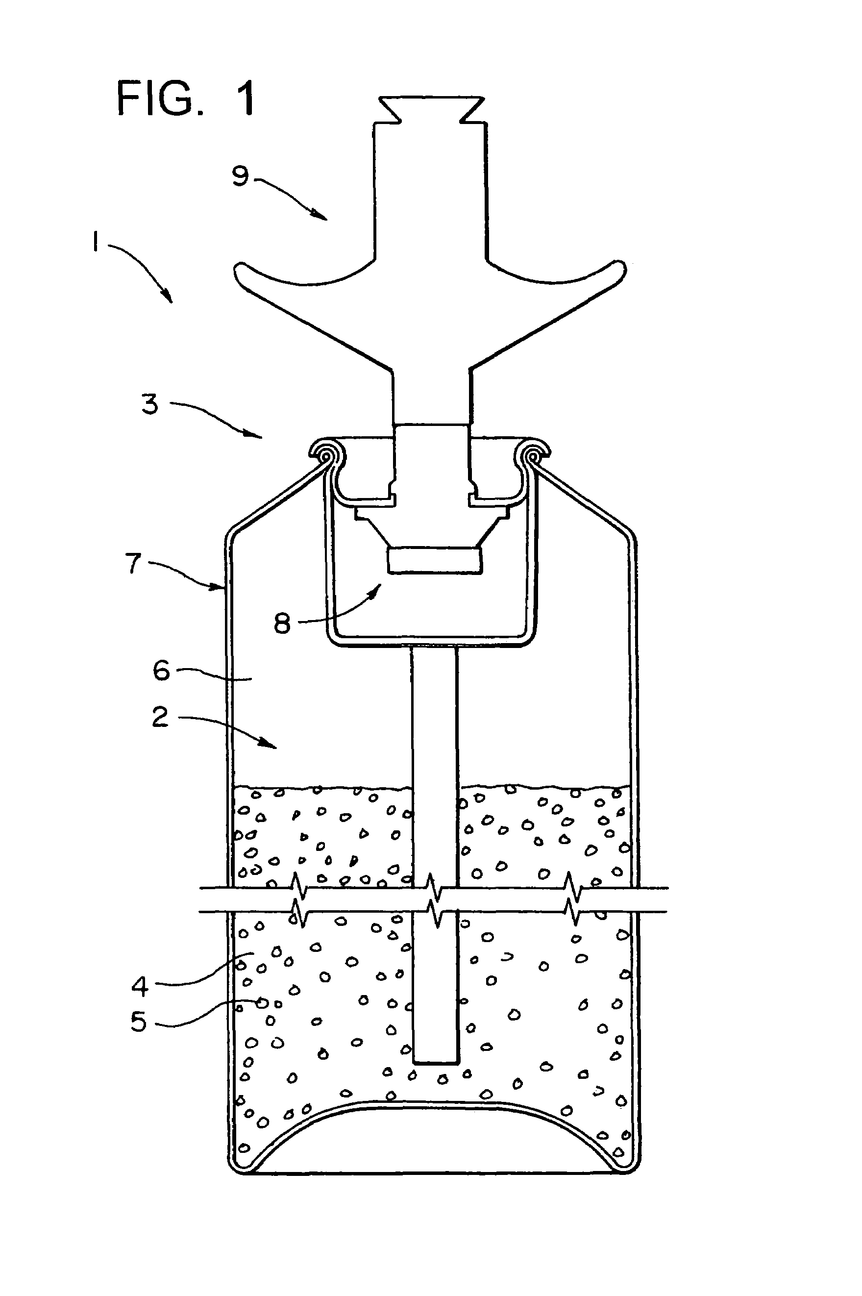
[0135]FIG. 6 illustrates at 110 of the third embodiment of the present invention which is particularly adapted to apply an acoustic texture material to the surface of a ceiling. This apparatus 110 comprises a container 112 and a discharge assembly 114. The container 112 defines a chamber 116 having a texture material containing portion 118 and a propellant containing portion 120. In this third embodiment, the texture material containing portion 118 is located in the bottom part of the chamber 116 since the apparatus 110 is normally operated in a vertically aligned position so that the texture material 122 is positioned by gravity in the lower part of the chamber 116. The propellant containing portion 120 is in the upper part of the chamber 116, and the propellant 124 is a gaseous substance which is substantially inert, such as nitrogen or atmospheric air, relative to the texture material 122. There is a pressure interface 126 between the upper surface 28 of the te...


PUM


Abstract

An aerosol device for dispensing texture material for matching existing acoustical ceiling texture. The device comprises a container, a valve assembly, a dispensing nozzle, a hardenable material, and pressurized inert gas as a propelling mechanism. The hardenable material and pressurized inert gas are placed into the container. When the valve assembly is opened, the inert gas forces the hardenable material out of the container through the dispensing nozzle. The dispensing nozzle diverts at least a portion of the hardenable material exiting the container to develop a spray suitable for the application of the hardenable material onto the ceiling surface being textured. The hardenable material preferably comprises at least water, filler, binder, and polystyrene particles. The inert gas is preferably nitrogen.

Description

RELATED APPLICATIONS[0001]This application is a continuation of U.S. Ser. No. 10 / 691,897 filed Oct. 22, 2003, now U.S. Pat. No. 7,014,073 which is a continuation of U.S. Ser. No. 10 / 047,041 filed Jan. 14, 2002, now U.S. Pat. No. 6,641,005, which is a continuation of U.S. Ser. No. 09 / 703,409 filed Oct. 31, 2000, now U.S. Pat. No. 6,352,184 which is a continuation of U.S. Ser. No. 09 / 203,547 filed Dec. 1, 1998, now U.S. Pat. No. 6,152,335, which is a continuation-in-part of U.S. Ser. No. 08 / 950,202 filed Oct. 14, 1997, now abandoned, which is a continuation of Ser. No. 08 / 782,142 filed Jan. 10, 1997, now abandoned, which is a continuation of Ser. No. 08 / 534,344 filed Sep. 27, 1995, now abandoned, which is a continuation of Ser. No. 08 / 496,386 filed Jun. 29, 1995, now abandoned, which is a continuation of Ser. No. 08 / 327,111 filed Oct. 21, 1994, now abandoned, which is a continuation-in-part of Ser. No. 08 / 216,155 filed Mar. 22, 1994, now U.S. Pat. No. 5,450,983, which is a continuatio...

Claims


Application Information

Patent Timeline
Patent Type & Authority Patents(United States)
IPC IPC(8): B65D83/00B05B1/02B05B1/12B05B1/16B05B1/34B05D1/02B05D5/06B65D83/14B65D83/16B65D83/30
CPCB05B1/02B65D83/546B05B1/12B05B1/1645B05B1/1654B05B1/26B05B1/34B05B7/2435B05D1/02B05D5/061B65D83/20B65D83/201B65D83/206B65D83/30B65D83/303B65D83/42B65D83/46B65D83/48B65D83/525B65D83/54B65D83/60B65D83/62B65D83/64B65D83/752E04F21/12B05B1/04
Inventor STERN, DONALD J.TRYON, JAMES A.
Owner HOMAX PRODS
Why Eureka
Try Eureka