Deformable curvature mirror with unipolar-wiring

a curvature mirror and unipolar technology, applied in the field of deformation curvature mirrors, can solve the problems of large fitting errors, limited accuracy and degree of optical correction that can be applied to stack actuator type mirrors, and complex prior techniques and systems. achieve the effect of more control over the deformation of the mirror

Inactive Publication Date: 2005-04-05
EOS DEFENSE SYST USA INC
View PDF26 Cites 12 Cited by
  • Summary
  • Abstract
  • Description
  • Claims
  • Application Information

AI Technical Summary

Benefits of technology

[0011]In another embodiment, a gold layer is between the two plates. A variable unipolar voltage is selectively

Problems solved by technology

Such prior techniques and systems are typically complex and expensive, as well as having various inherent deficiencies.
In addition to the deficiencies of the prior art wavefront sensors, the deformable mirrors that are controlled by those wavefront sensors for adaptive optics also include numerous deficiencies.
The push rods tend to produce a deformation which is nearly a straight line on the mirror surface between each pair of adjacent push rods that results in large fitting errors When a small number of actuators are used.
Moreover, the number of push rods and, therefore, the closeness of the push rods is physically limited, a

Method used


Image

  • Deformable curvature mirror with unipolar-wiring
  • Deformable curvature mirror with unipolar-wiring
  • Deformable curvature mirror with unipolar-wiring

Examples


third embodiment

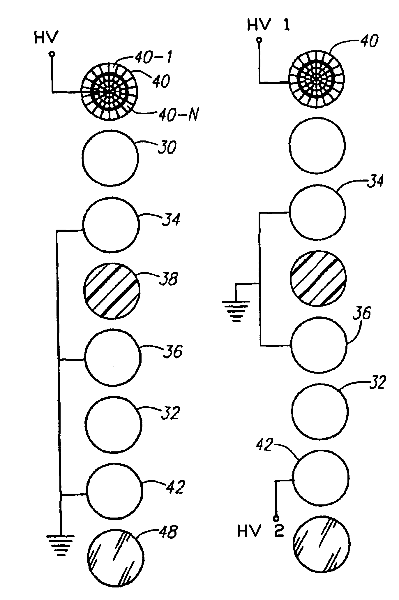
[0047]Central gold layers 34 and 36 are connected to a second unipolar voltage source UV 2. The second unipolar source UV 2 provides a unipolar voltage to central gold layers 34 and 36. Preferably the voltage provided by unipolar voltage source UV 2 is chosen such that the voltage across the electro-restrictive plate 32 to the gold layer 42 is in the same direction of the polarity of the electro-restrictive plate 32. Gold layer 42 is connected to electrical ground. In one embodiment, the second unipolar source UV 2 is held at a constant value, and varying the voltage provided by the first unipolar voltage source UV 1 controls the curvature of the mirror. In another embodiment, both unipolar voltage sources UV 1 and UV 2 are varied to control the curvature of the mirror. In yet a third embodiment, the first unipolar source UV 1 is held at a constant value, and the curvature of the mirror is controlled by varying the voltage provided by the second unipolar voltage source UV 2.

[0048]FI...

embodiment 14

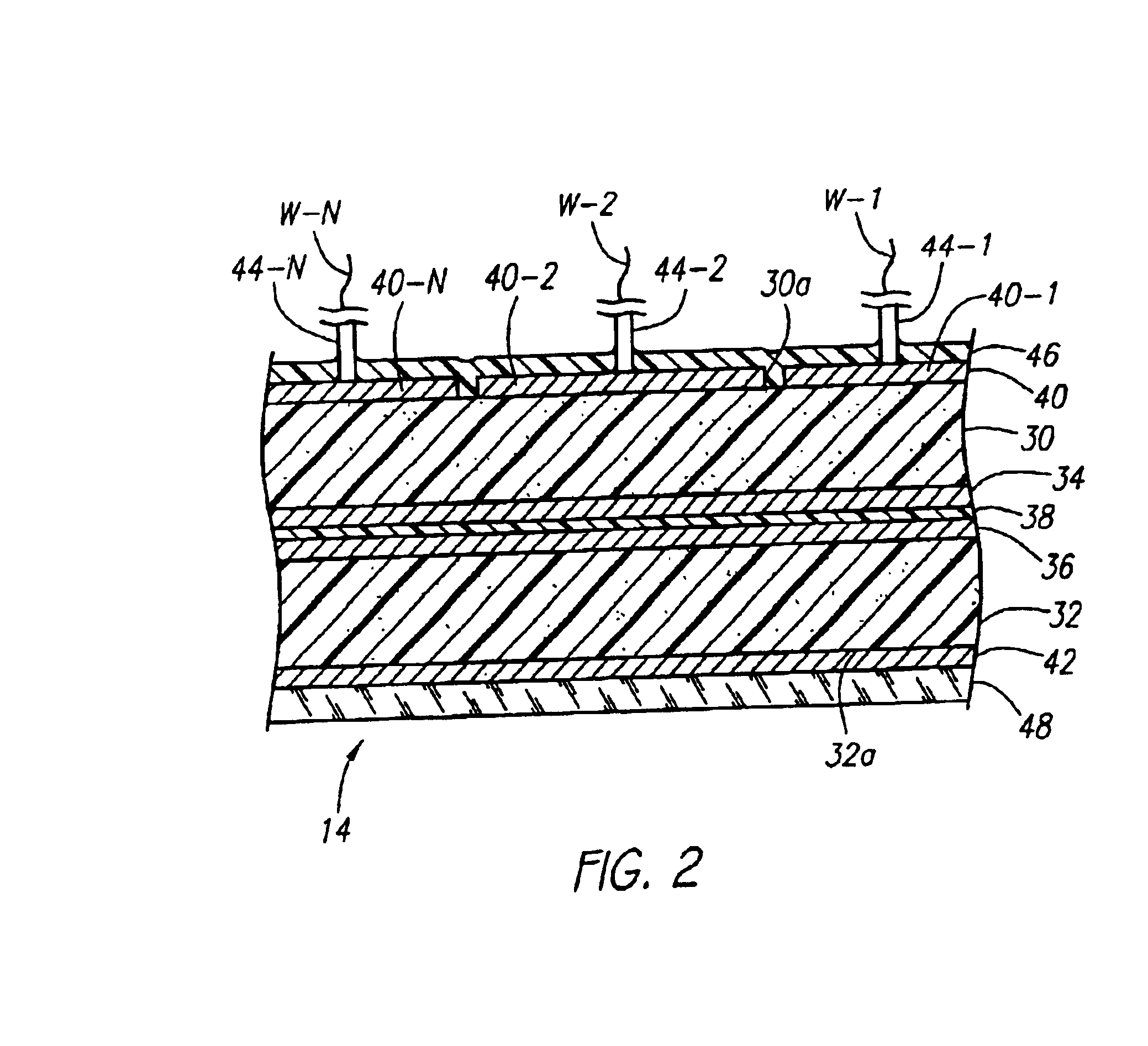
[0049]FIG. 8A illustrates the mirror embodiment 14 of FIG. 7F with equal electric field strengths across both plates 30 and 32. For example, gold layer 42 may be at ground, with no voltage applied to gold layer 34, and no voltage applied to electrode segment 40-1. This results, as shown in FIG. 8A, in a deformable mirror 14 that is not curved. In the previous example, each electro-restrictive plate has zero electric field across it. Alternately, equal nonzero electric fields across plates 30 and 32 may be applied. If the electric field strength across gold layers 42 and 34 is equal to the electric field strength between gold layer 34 and electrode 40-1, there is no curvature in the mirror. For example, assuming both plates 30 and 32 are of equal thickness, if 100 volts were applied to gold layer 34 and 200 volts applied to electrode 40-1, the voltage difference across both plates 30 and 32 would be 100 volts. This would result in equal field strengths across plates 30 and 32, and an...


PUM


Abstract

A deformable curvature mirror capable of controlled deformation by applying unipolar electrical voltages to electrode segments on the back of the mirror. Two plates of an electro-restrictive material, such as PZT or PMN, are jointed together. One plate has a pattern of a plurality of electrode segments on the outer surface with each electrode segment having a separate electrical terminal for applying a variable unipolar electrical voltage thereto for causing variable expansion of the plate and thereby selectively deforming that plate and, in turn, the deformable curvature mirror.

Description

CROSS-REFERENCE TO RELATED APPLICATIONS[0002]This application is a continuation-in-part of U.S. patent application Ser. No. 09 / 769,988, filed on Jan. 25, 2001, now issued as U.S. Pat. No. 6,464,364, which claimed priority from U.S. Provisional Application Ser. No. 60 / 178,416, filed Jan. 27, 2000.BACKGROUND[0003]1. Field of the Invention[0004]The present invention relates to a deformable curvature mirror that is capable of controlled deformation by the application of electrical voltages to the mirror and, in particular, is directed to such a mirror that is for use in an adaptive optics system having a wavefront sensor for controlling the deformation of the curvature mirror.[0005]2. Background of the Invention[0006]There are various adaptive optics methods and devices which include a wavefront sensor for sensing the aberrations in the wavefront of light waves and then correcting or compensating for those aberrations, such as the atmospheric aberrations that effect the viewing of stars...

Claims


Application Information

Patent Timeline
IPC IPC(8): G02B26/06G02B26/00G02B26/08
CPCG02B26/0825G02B26/06
Inventor GRAVES, J. ELONNORTHCOTT, MALCOLM J.
Owner EOS DEFENSE SYST USA INC
Why Eureka
Try Eureka