LED assembly and use thereof

a technology of light-emitting diodes and led assemblies, which is applied in the direction of fixed installation, lighting and heating equipment, lighting support devices, etc., can solve the problems of inefficient thermal dissipation and overheating, short circuit, and thermal damage to adjacent or surrounding components

Active Publication Date: 2009-01-27
HONG KONG APPLIED SCI & TECH RES INST
View PDF14 Cites 28 Cited by
  • Summary
  • Abstract
  • Description
  • Claims
  • Application Information

AI Technical Summary

Problems solved by technology

However, when a plurality of light sources such as LEDs, consumes electricity at the same time, the heat generated from the light sources often causes disadvantages and problems, including creation of a short circuit, thermal damages to adjacent or surrounding components.
As will be thus appreciated, inefficient thermal dissipation and overheating are common drawbacks of the conventional light sources.
However, such heat sinks and cooling agents render an LED assembly design unnecessarily complicate and bulky.

Method used


Image

  • LED assembly and use thereof
  • LED assembly and use thereof
  • LED assembly and use thereof

Examples


Embodiment Construction

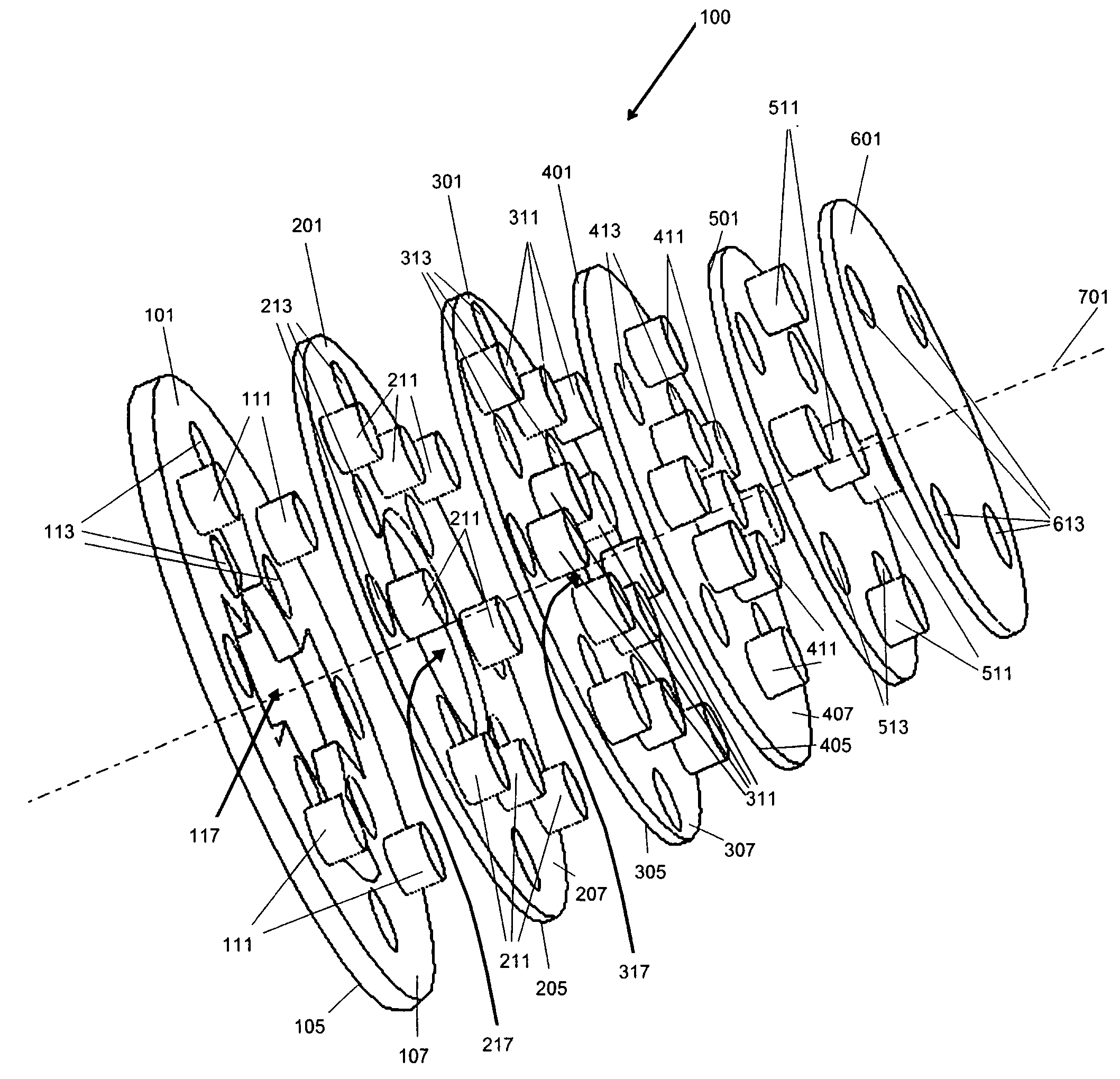
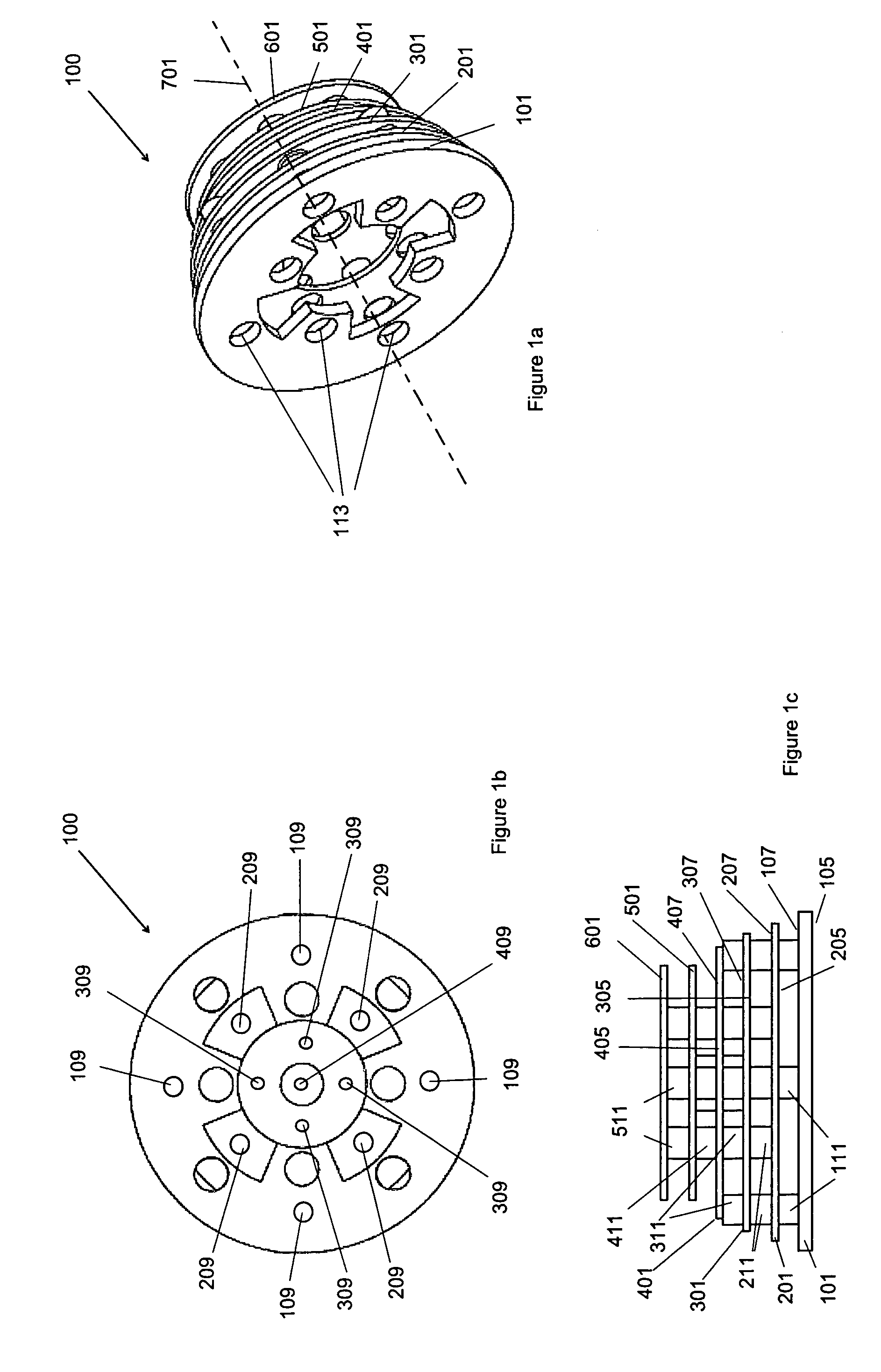
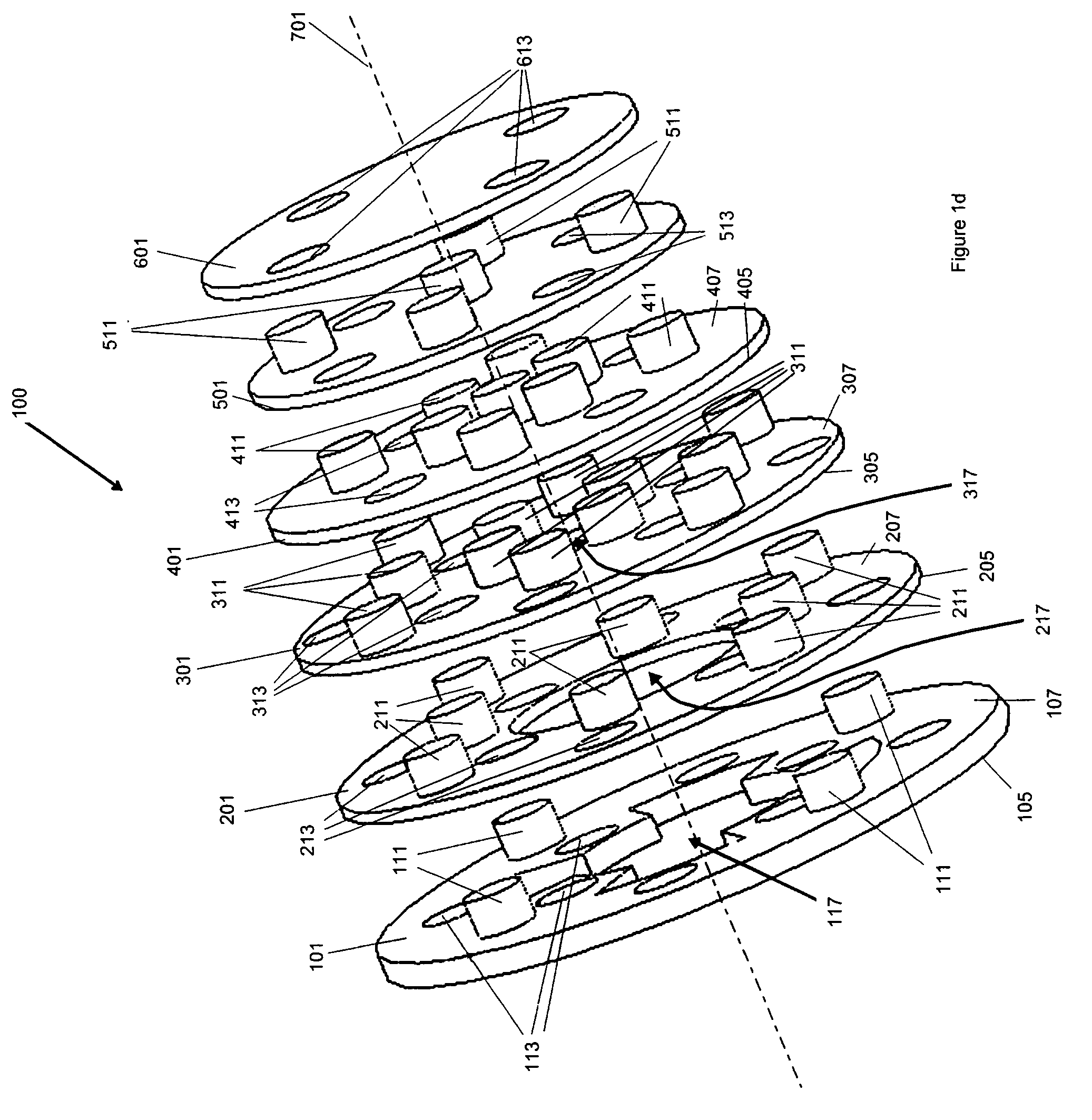
[0021]As shown in FIGS. 1a-d, an exemplary light emitting diode (LED) assembly embodiment 100 according to the present invention has a multi stack of four LED substrates 101, 201, 301, 301 and a pair of electrical substrates 501, 601 substantially parallel to each other and stacked along an axis 701 being substantially perpendicular to and passing though centers (not shown) of the layers. In the exemplary embodiment, each layer has a substantially circular shape, but it will be understood that different shapes will be equally applicable depending upon the required application of the assembly.

[0022]Each LED substrate 101, 201, 301, 401 is substantially planar having an upper surface 105, 205, 305, 405 and a lower surface 107, 207, 307, 407. LEDs 109, 209, 309, 409 are mounted on the respective upper surfaces 105, 205, 305, 405 and emit lights in a substantially unanimous light emitting direction (not shown) substantially parallel to axis 701 and from electrical substrate 601 towards ...


PUM


Abstract

A light emitting diode (LED) assembly includes a first substrate carrying a first plurality of LEDs mounted thereon and a second substrate spaced apart from the first substrate. The second substrate carries a second plurality of LEDs thereon. The first and second substrates are thermally connected for thermal distribution between the substrates.

Description

FIELD OF THE INVENTION[0001]The present invention relates to a light emitting diode assembly with improved thermal dissipation performance.BACKGROUND OF THE INVENTION[0002]Light emitting diodes (LEDs) have been widely used as light sources in lighting apparatus. However, when a plurality of light sources such as LEDs, consumes electricity at the same time, the heat generated from the light sources often causes disadvantages and problems, including creation of a short circuit, thermal damages to adjacent or surrounding components. As will be thus appreciated, inefficient thermal dissipation and overheating are common drawbacks of the conventional light sources.[0003]Heat sinks and cooling agents have been proposed in, for example, U.S. Pat. No. 6,880,956, entitled “Light source with heat transfer arrangement” and issued to Zhang on Apr. 19, 2005. However, such heat sinks and cooling agents render an LED assembly design unnecessarily complicate and bulky.[0004]It is an object of the p...

Claims


Application Information

Patent Timeline
Patent Type & Authority Patents(United States)
IPC IPC(8): H01L29/18
CPCF21K9/00F21V29/83H05K1/144F21V29/2212F21Y2111/008H05K1/0203H05K1/0272H05K2201/042H05K2201/09063H05K2201/10106H05K2201/10242H05K2201/2036H01L2924/0002F21Y2101/02H01L2924/00F21Y2115/10F21Y2107/60F21V29/76
Inventor LU, MINGWU, KAI CHIUZHANG, ZHIKUANWU, ENBOA
Owner HONG KONG APPLIED SCI & TECH RES INST
Why Eureka
Try Eureka