
Ventilated prosthesis system

a prosthesis and ventilation technology, applied in the field of ventilation prosthesis systems, can solve the problems of requiring time to be constructed, difficult to don and make the residual limb uncomfortable, and bulky prosthesis sockets on residual limbs, etc., and achieves the effect of slim profile and easy to don

Active Publication Date: 2009-02-10
KAUPTHING BANK
View PDF16 Cites 108 Cited by
  • Summary
  • Abstract
  • Description
  • Claims
  • Application Information

AI Technical Summary

Benefits of technology

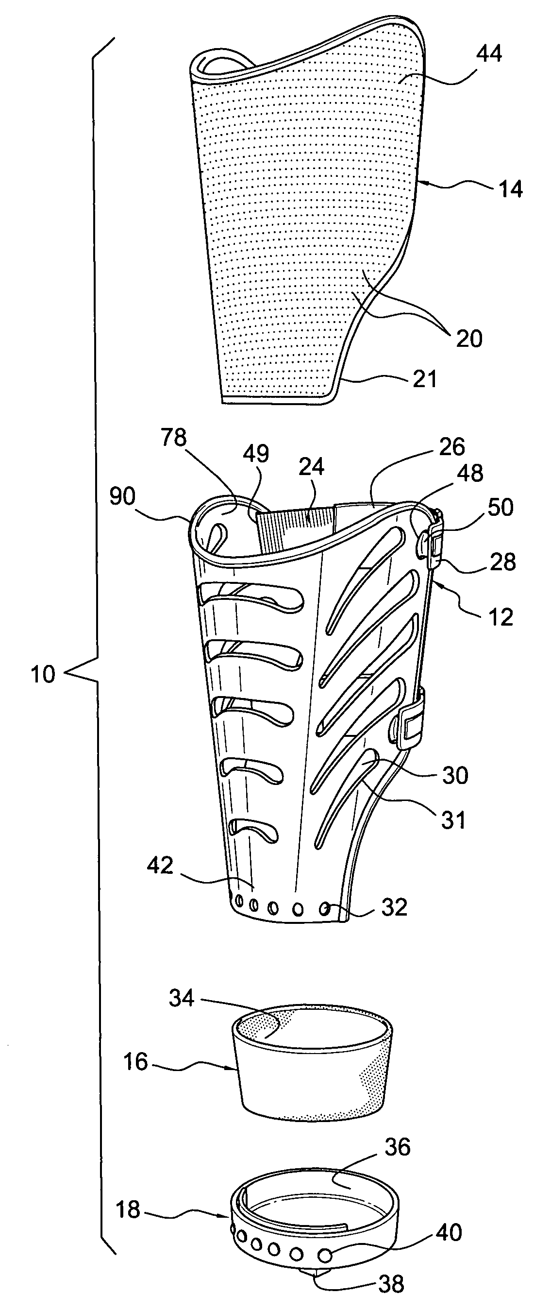
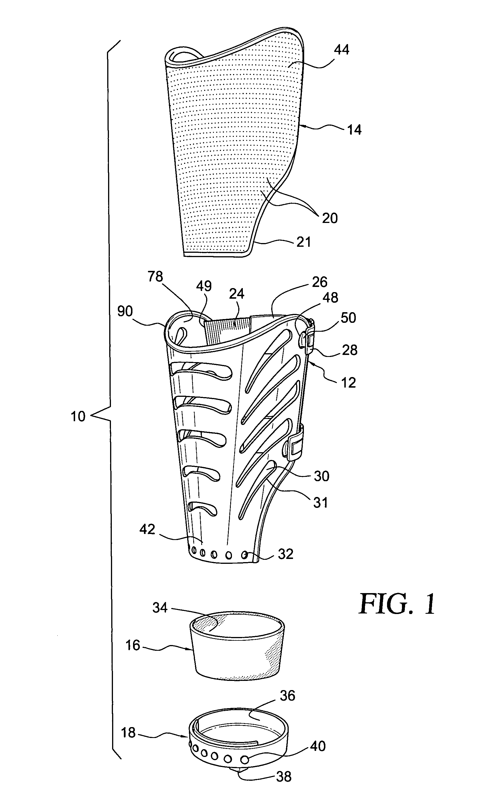
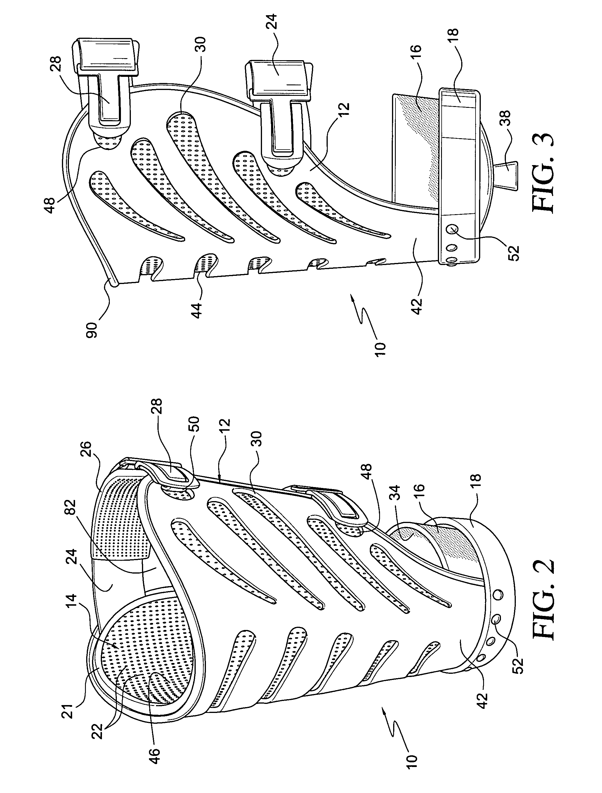
"The present invention is about a prosthesis system that can be easily donned and ventilated. It has adjustable settings and is lightweight and slim. It can be used as a temporary or permanent prosthesis socket system. The system includes a ventilated shell and a compliant spacer element with a frictional feature. A connector is attached to the shell, and a retainer is inserted into the connector to secure the system. The shell can be a single or two-piece design, and the spacer element can be a tubular liner. The system can be custom fitted or defined by a definitive socket. Various components of the system are described in more detail below."

Problems solved by technology

Existing prosthetic sockets on residual limbs tend to be bulky and cumbersome to wear.
They may also be difficult to don and make the residual limb uncomfortable when worn due to a lack of ventilation.
Moreover, most prosthetic sockets are permanently formed, thereby not accounting for swelling of a residual limb.
These sockets also require time to be constructed, and there are very few socket options for new amputees prior to receiving a socket after surgery.

Method used


Image

  • Ventilated prosthesis system
  • Ventilated prosthesis system
  • Ventilated prosthesis system

Examples


Embodiment Construction

[0022]A. Overview

[0023]A better understanding of different embodiments of the invention may be had from the following description read in conjunction with the accompanying drawings in which like reference characters refer to like elements.

[0024]While the disclosure is susceptible to various modifications and alternative constructions, certain illustrative embodiments are shown in the drawings and will be described below in detail. It should be understood, however, that there is no intention to limit the disclosure to the specific embodiments disclosed, but on the contrary, the intention is to cover all modifications, alternative constructions, combinations, and equivalents falling within the spirit and scope of the disclosure and defined by the appended claims.

[0025]It will be understood that, unless a term is expressly defined in this patent to possess a described meaning, there is no intent to limit the meaning of such term, either expressly or indirectly, beyond its plain or ordi...


PUM


Abstract

A prosthesis system including a ventilated shell, and a substantially compliant, ventilated spacer element that defines a first surface having a frictional feature. The spacer element is arranged to secure to an internal surface of the shell. The prosthesis system also includes a connector that is secured to a distal end of the shell, and a retainer supported by the connector so as to extend into a cavity formed by the shell.

Description

CROSS REFERENCE TO RELATED APPLICATIONS[0001]This application claims the benefit of priority of U.S. provisional application 60 / 785,344, filed on Mar. 24, 2006.FIELD OF THE INVENTION[0002]This invention relates to a ventilated prosthesis system for a residual limb.BACKGROUND OF RELATED ART[0003]Existing prosthetic sockets on residual limbs tend to be bulky and cumbersome to wear. They may also be difficult to don and make the residual limb uncomfortable when worn due to a lack of ventilation. Moreover, most prosthetic sockets are permanently formed, thereby not accounting for swelling of a residual limb. These sockets also require time to be constructed, and there are very few socket options for new amputees prior to receiving a socket after surgery.[0004]It is desirable to provide a simplified and compact prosthesis system that overcomes the drawbacks over known prosthesis systems. Further, it is desirable to provide a prosthesis system that can be worn temporarily and adjusted acc...

Claims


Application Information

Patent Timeline
Patent Type & Authority Patents(United States)
IPC IPC(8): A61F2/60
CPCA61F2/78A61F2/80A61F2002/5083A61F2002/7818A61F2002/7862A61F2002/7881A61F2240/001A61F2250/0024
Inventor EINARSSON, PALMI
Owner KAUPTHING BANK
Learn More