Fluid supply arrangement for a rolling-traction continuously variable ratio transmission unit

a technology of continuous variable ratio and fluid supply arrangement, which is applied in the direction of machines/engines, drip or splash lubrication, and gating, etc., can solve the problems of thin fluid layer between disc and roller, excessive wear, and impair the performance of traction fluid

Active Publication Date: 2009-02-17
ALLISON TRANSMISSION INC
View PDF9 Cites 46 Cited by
  • Summary
  • Abstract
  • Description
  • Claims
  • Application Information

AI Technical Summary

Problems solved by technology

Maintenance of the film is of primary importance since direct roller/disc contact would cause excessive wear.
Excessive temperatures can (1) damage the rollers themselves (the steel from which they are formed undergoing changes under sustained high temperatures); and (2) impair the performance of the traction fluid, high temperatures and consequent low fluid viscosity leading to a thinner fluid layer between disc and roller, and to higher slip between these components.
Sustained high temperatures can also cause the fluid properties to change over time in an undesirable manner.
Prov

Method used


Image

  • Fluid supply arrangement for a rolling-traction continuously variable ratio transmission unit
  • Fluid supply arrangement for a rolling-traction continuously variable ratio transmission unit
  • Fluid supply arrangement for a rolling-traction continuously variable ratio transmission unit

Examples


Embodiment Construction

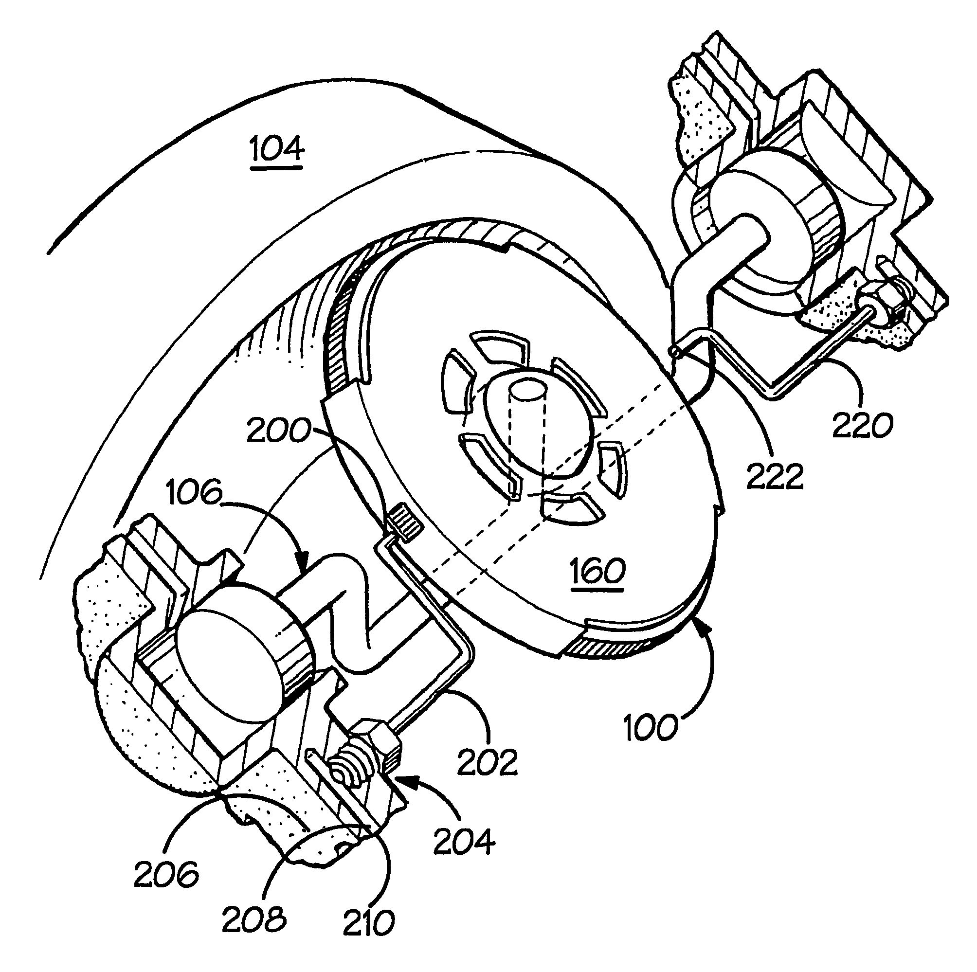
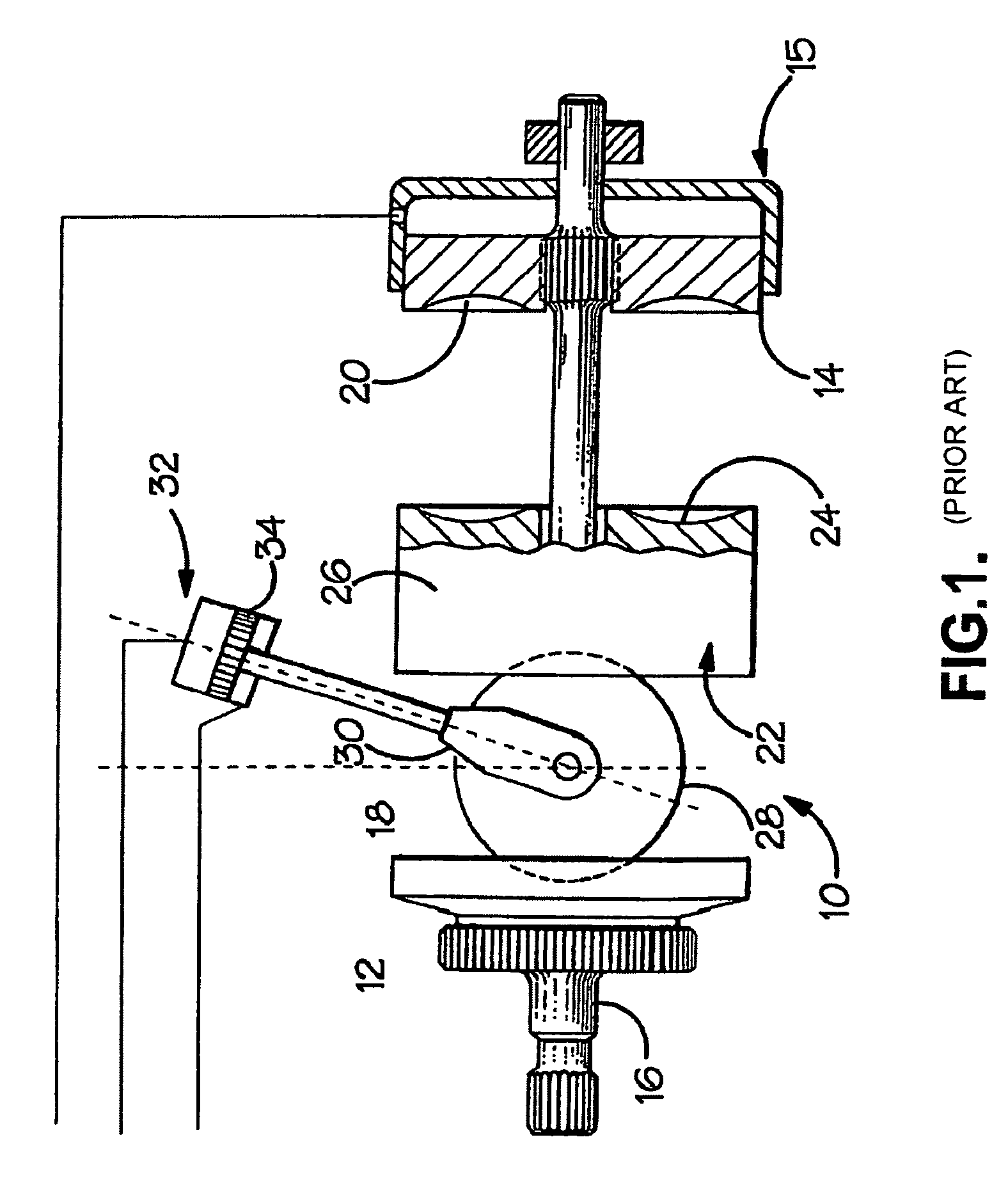
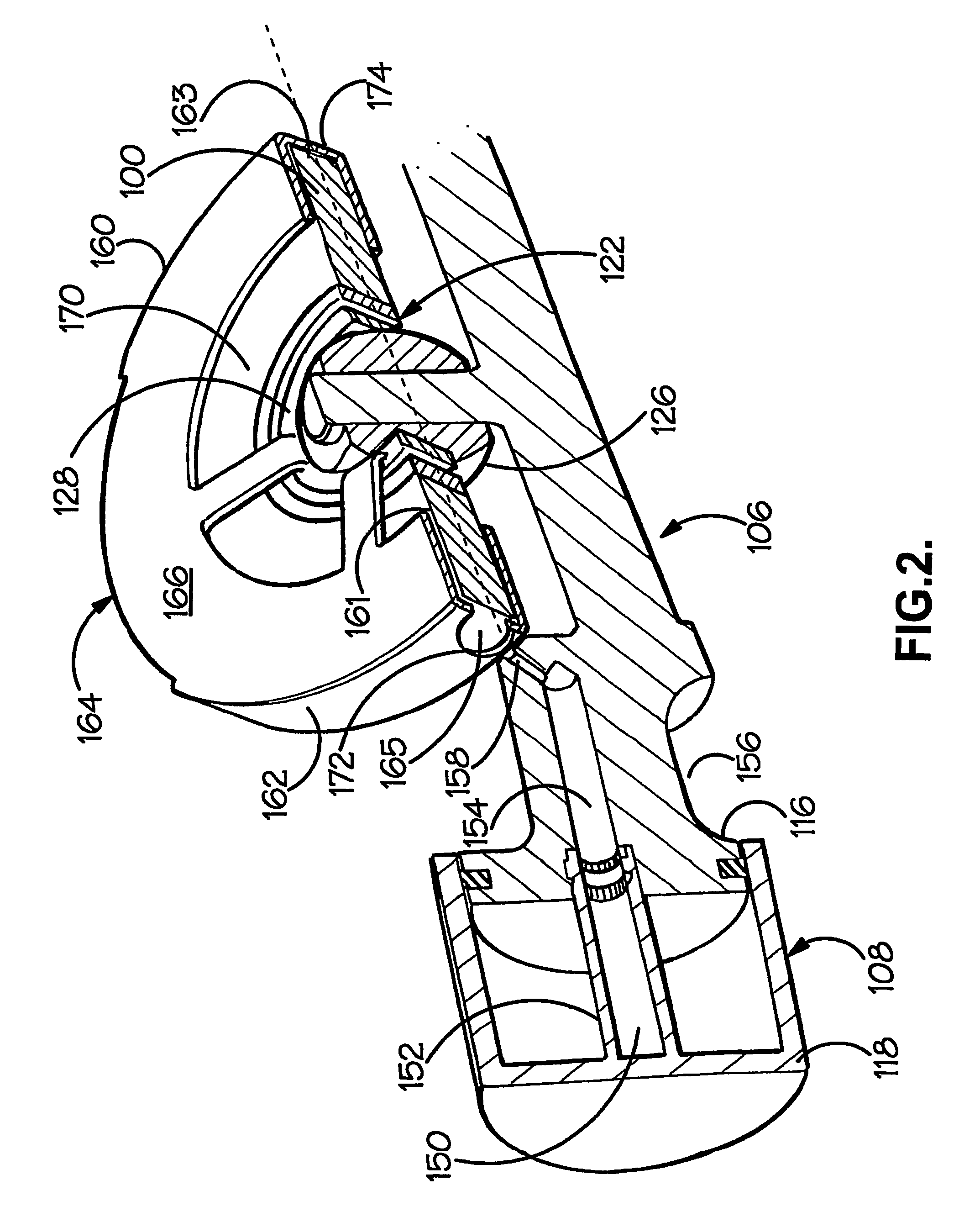
[0023]The variator construction illustrated in FIGS. 2 and 3 differs somewhat from that of FIG. 1 and its construction and operation will be briefly explained before the fluid supply arrangement itself is considered. Each of the three rollers 100 in the variator cavity 102 defined between variator disc 104 and its counterpart disc (omitted from FIG. 3) is mounted upon a respective carriage 106 which is acted on by two hydraulic actuators 108, 110. The carriages are not free to rotate to accommodate the required precession of the roller axis. Instead the orientation of the carriages is constrained. To appreciate why this is so, note firstly that due to the variator geometry the center of each roller always lies on a circle 112 which is the center circle of the toroidal cavity defined by the discs, as is well known to those skilled in the art Any rotational movement of the carriage could only be about a carriage axis 114 (see FIG. 3) connecting the centers of the actuators 108, 110, s...


PUM


Abstract

A fluid display arrangement is disclosed for a rolling-traction continuously-variable ratio transmission unit in which drive is transmitted from one race to another by at least one rotating roller whose outer circumference engages the races, the fluid supply arrangement comprising a shroud mounted in proximity to the roller and a fluid supply conduit, and being characterised in that the shroud has an inner surface providing a circumferential portion adjacent the roller's outer circumference and two radially extending portions adjacent respective flanks of the roller, a fluid receiving chamber being thereby defined between the roller and the shroud, and the fluid supply conduit being arranged to deliver fluid into the fluid receiving chamber.

Description

CROSS REFERENCE TO RELATED APPLICATIONS:[0001]This Application is a National Phase of International Application No. PCT / GB03 / 00281, filed on Jan. 24, 2003, which claims priority from Great Britain patent application No. 0201631.9, filed on Jan. 24, 2002.BACKGROUND OF THE INVENTION[0002]The present invention relates generally to continuously variable transmission units (“variators”) of rolling-traction type and more specifically to an arrangement for supply of fluid to a roller of such a variator.[0003]Major components of a known toroidal-race rolling-traction variator 10 are illustrated in FIG. 1. Here, two input discs 12, 14 are mounted upon a drive shaft 16 for rotation therewith and have respective part toroidal surfaces 18, 20 facing toward corresponding part toroidal surfaces 22, 24 formed upon a central output disc 26. The output disc is journalled such as to be rotatable independently of the shaft 16. Drive from an engine or other prime mover, input via the shaft 16 and input...

Claims


Application Information

Patent Timeline
IPC IPC(8): F16H57/04F16H1/00F16H15/38
CPCF16H15/38F16H57/043F16H57/049
Inventor GREENWOOD, CHRISTOPHER JOHNFLAXMAN, ROBERT JOHN BONNERBRIFFETT, GRAHAMMACPHERSON, IAN
Owner ALLISON TRANSMISSION INC
Why Eureka
Try Eureka