Tubular acoustic silencer

a acoustic silencer and tube technology, applied in the direction of air cleaner and silencer combination, combustion-air/fuel-air treatment, separation process, etc., can solve the problems of variable and inconsistent air flow velocity profiles, and achieve the effect of increasing the demand for sound attenuation and cost-effectiveness

Active Publication Date: 2009-03-03
CUMMINS FILTRATION INC
View PDF38 Cites 22 Cited by
  • Summary
  • Abstract
  • Description
  • Claims
  • Application Information

AI Technical Summary

Problems solved by technology

In internal combustion engine applications, engine manufacturers are increasingly demanding filters which do not interfere with mass air flow sensors (MAFS) that are typically placed directly downstream from the filter cartridge and are sensitive to filter cartridge geometry / imperfections causing variable and inconsistent air flow velocity profiles.

Method used


Image

  • Tubular acoustic silencer
  • Tubular acoustic silencer
  • Tubular acoustic silencer

Examples


Embodiment Construction

Parent Application

[0031]The following description of FIGS. 1-12 is taken from the noted parent '775 application.

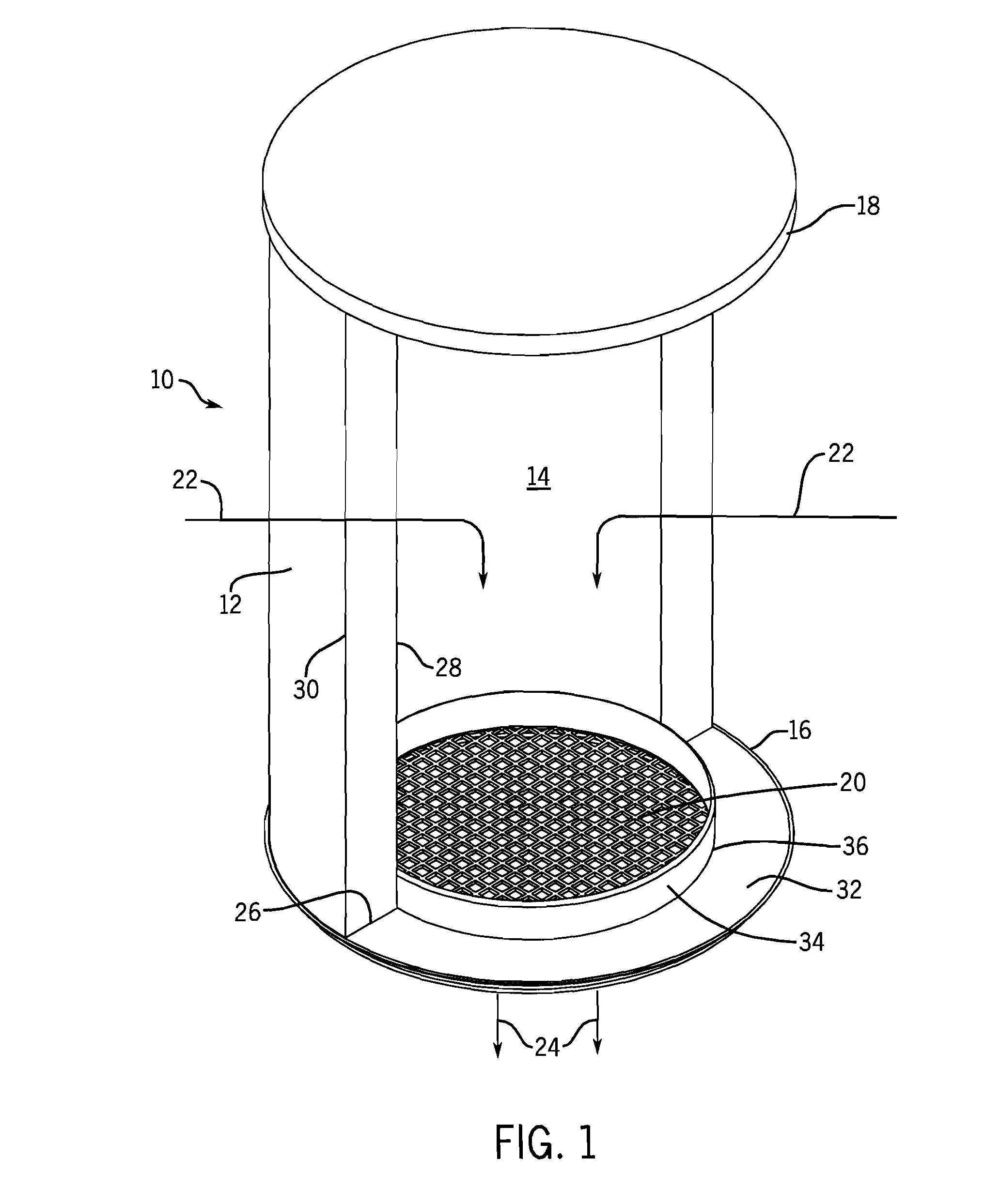
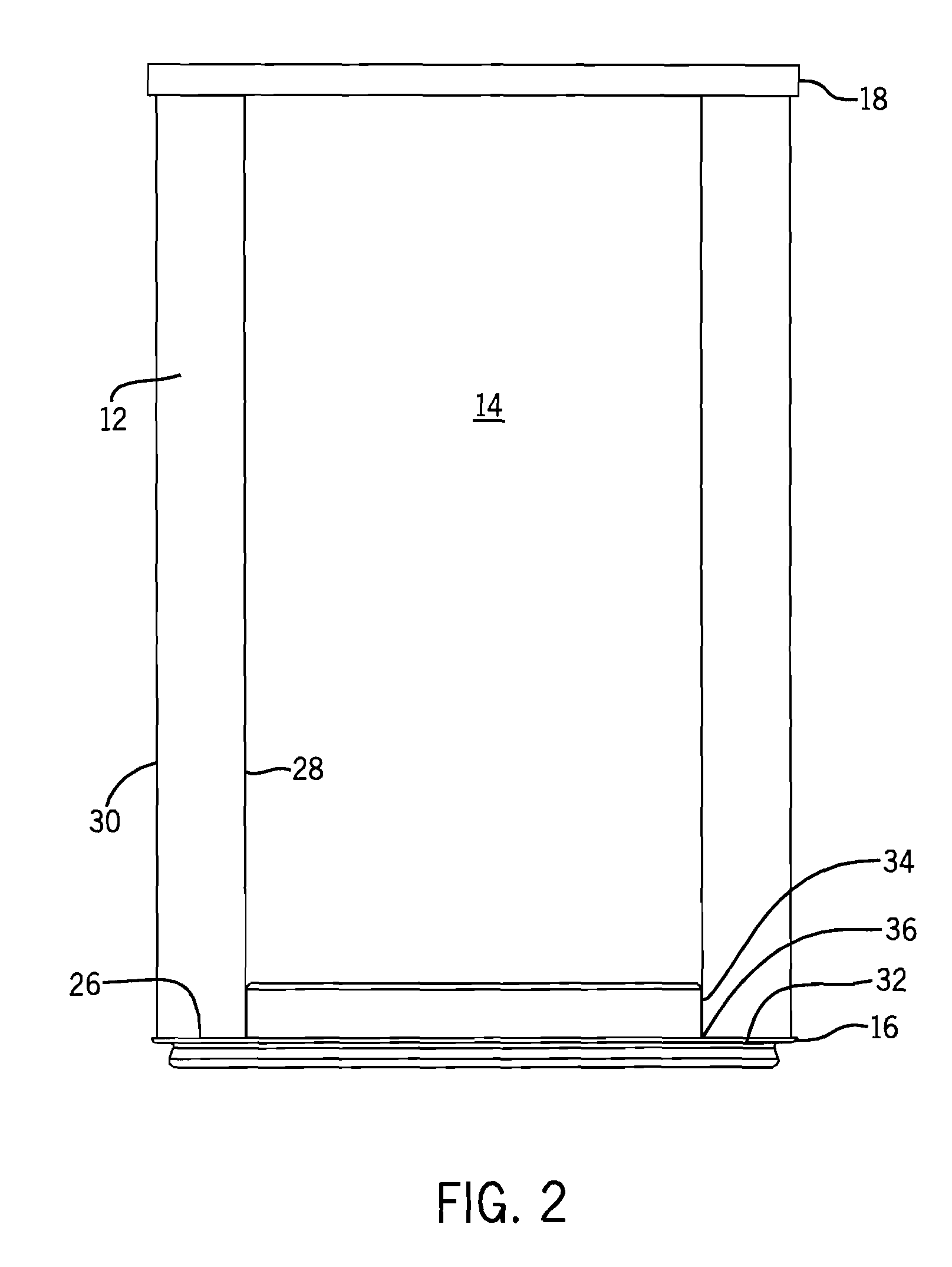
[0032]FIG. 1 shows an air filtration cartridge 10 including annular filter media 12 having a hollow interior 14 and extending axially between first and second distally opposite end caps 16 and 18. End cap 16 is an outlet end cap having flow straightening structure 20 integrally formed therewith and spanning hollow interior 14. Air flows radially inwardly as shown at arrows 22 through filter media. 12 into hollow interior 14 and then flows from hollow interior 14 axially through flow straightening structure 20 as shown at arrows 24. Flow straightening structure 20 is preferably provided by a grid or matrix having a plurality of openings or apertures therethrough guiding and straightening axial flow at 24 for reducing variability of outlet air flow velocity profile, i.e. providing a more uniform air flow velocity across the entire radial span of the filter cartridge outlet, ...


PUM

PropertyMeasurementUnit
radial widthaaaaaaaaaa
axial widthaaaaaaaaaa

Abstract

An acoustic silencer is provided by a tubular member extending along an axis and having a hollow interior defining an axial flow path therethrough. The tubular member has a sidewall with an interior face facing the hollow interior and having quarter wave resonators formed by blind holes therein.

Description

CROSS-REFERENCE TO RELATED APPLICATIONS[0001]The present application is a continuation-in-part of U.S. patent application Ser. No. 11 / 044,775, filed Jan. 27, 2005.BACKGROUND AND SUMMARY[0002]The present invention relates to tubular acoustic silencers.Parent Application[0003]The above noted parent '775 application relates to air filtration cartridges. Air filtration cartridges are known in the prior art and are typically provided by annular filter media having a hollow interior and extending axially between first and second distally opposite end caps, one of which is an outlet end cap, and the other of which may be closed. In internal combustion engine applications, engine manufacturers are increasingly demanding filters which do not interfere with mass air flow sensors (MAFS) that are typically placed directly downstream from the filter cartridge and are sensitive to filter cartridge geometry / imperfections causing variable and inconsistent air flow velocity profiles. In the case of ...

Claims


Application Information

Patent Timeline
Patent Type & Authority Patents(United States)
IPC IPC(8): F01N1/02E04B1/84F01N7/08F01N13/08
CPCB01D46/0045B01D46/2414F02M35/14F02M35/1211F02M35/1216F02M35/1255
Inventor CHENG, C. RAYMONDQUABILI, ZAKIR AHMADGUNDERSON, LARRY T.HOLZMANN, MARK V.
Owner CUMMINS FILTRATION INC
Why Eureka
Try Eureka