Tools for implanting an artificial vertebral disk

a technology for implants and vertebrae, applied in the field of tools for implanting artificial vertebrae, can solve the problems of not being able to provide an implant that restores and achieves the effect of restoring a wide range of natural movemen

Inactive Publication Date: 2009-03-03
KYPHON
View PDF466 Cites 101 Cited by
  • Summary
  • Abstract
  • Description
  • Claims
  • Application Information

AI Technical Summary

Problems solved by technology

None of these solutions provide an implant that restores a wide range of natural movement.

Method used


Image

  • Tools for implanting an artificial vertebral disk
  • Tools for implanting an artificial vertebral disk
  • Tools for implanting an artificial vertebral disk

Examples


Embodiment Construction

[0025]The following description is presented to enable any person skilled in the art to make and use the invention. Various modifications to the embodiments described will be readily apparent to those skilled in the art, and the principles defined herein can be applied to other embodiments and applications without departing from the spirit and scope of the present invention as defined by the appended claims. Thus, the present invention is not intended to be limited to the embodiments shown, but is to be accorded the widest scope consistent with the principles and features disclosed herein. To the extent necessary to achieve a complete understanding of the invention disclosed, the specification and drawings of all patents, patent publications, and patent applications cited in this application are incorporated herein by reference.

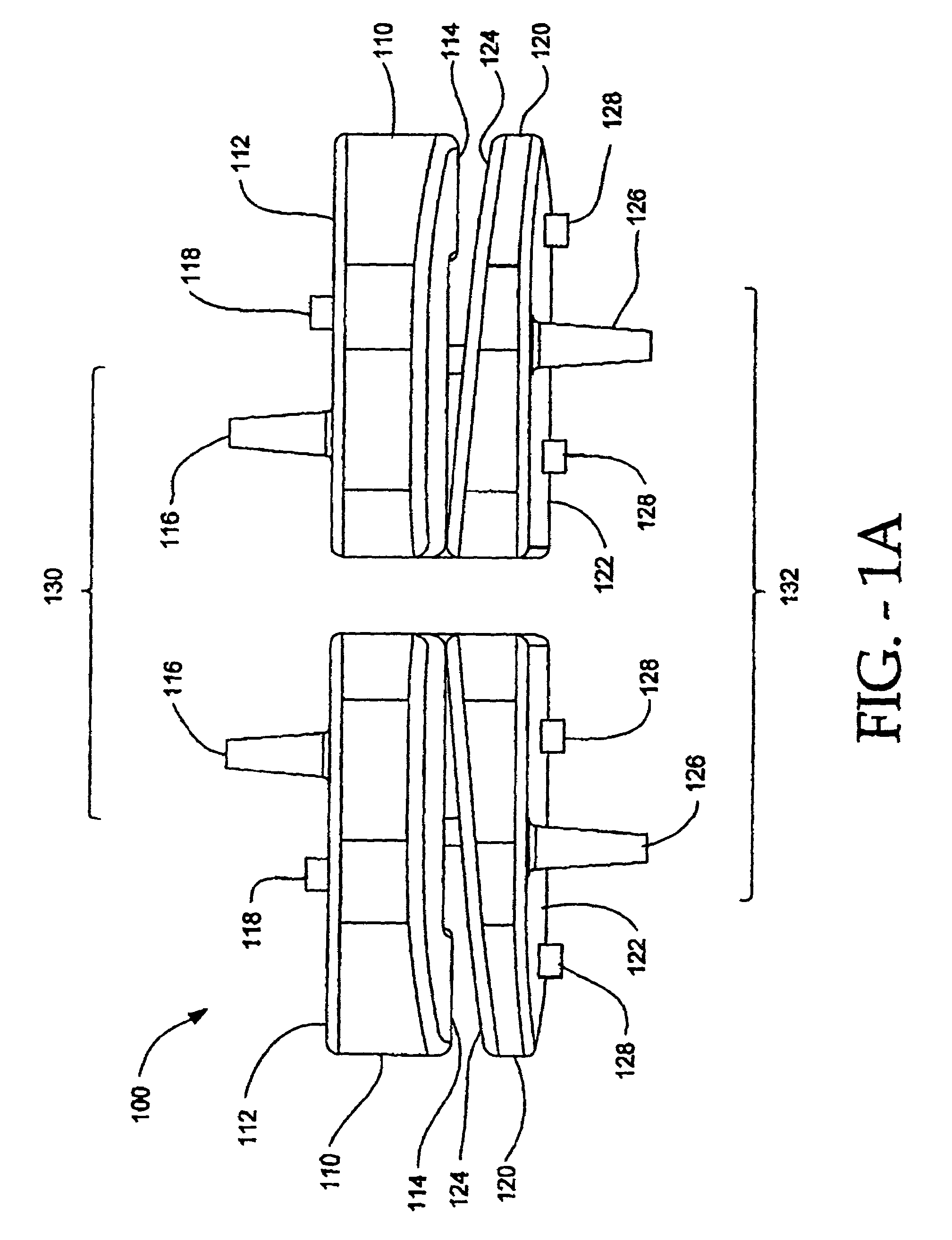
[0026]Turning now to FIG. 1A, a posterior view of an intervertebral implant 100 is depicted having a four-piece configuration. Although, as will be appreciat...


PUM


Abstract

This invention relates to tools for preparing vertebral bodies in the spine for the implantation of an artificial vertebral disk replacement and related method. A first tool is disclosed that prepares the vertebral bodies for implantation by cutting offset channels in the vertebral bodies. The second tool holds two plates of the implant during the implantation process. This invention also relates to an artificial vertebral disk replacement, a method of operation, and a method of implanting.

Description

CLAIM OF PRIORITY[0001]This application claims priority to U.S. Provisional Application No. 60 / 422,011, filed on Oct. 29, 2002, entitled “TOOLS FOR IMPLANTING AN ARTIFICIAL VERTEBRAL DISK AND METHOD”.CROSS-REFERENCE TO RELATED APPLICATIONS[0002]This application is related to U.S. Provisional Patent Application No. 60 / 422,039, filed Oct. 29, 2002, entitled “ARTIFICIAL VERTEBRAL DISK REPLACEMENT IMPLANT WITH TRANSLATING PIVOT PONT AND METHOD”, U.S. patent No. 7,083,649, filed Oct. 14, 2003, entitled “ARTIFICIAL VERTEBRAL DISK REPLACEMENT IMPLANT WITH TRANSLATING PIVOT POINT AND METHOD, U.S. Provisional Patent Application No. 60 / 422,021, filed Oct. 29, 2002, entitled “ARTIFICIAL VERTEBRAL DISK REPLACEMENT IMPLANT WITH CROSSBAR SPACER AND METHOD”, U.S. patent application Ser. No. 10 / 684,668,filed Oct. 14, 2003, entitled “ARTIFICIAL VERTEBRAL DISK REPLACEMENT IMPLANT WITH CROSSBAR SPACER AND METHOD”, U.S. Provisional Patent Application No. 60 / 422,022, filed Oct. 29, 2002, entitled “ARTIF...

Claims


Application Information

Patent Timeline
Patent Type & Authority Patents(United States)
IPC IPC(8): A61B17/00A61B17/16A61B17/32A61B17/88A61FA61F2/00A61F2/30A61F2/44A61F2/46
CPCA61B17/1671A61F2/4425A61F2/4611A61F2002/30224A61F2002/3065A61F2002/30654A61F2002/30662A61F2002/30665A61F2002/30808A61F2002/30892A61F2002/30904A61F2002/443A61F2002/448A61F2002/4627A61F2230/0069
Inventor ZUCHERMAN, JAMES F.HSU, KEN Y.WINSLOW, CHARLES J.YERBY, SCOTT A.MITCHELL, STEVEFLYNN, JOHN
Owner KYPHON
Why Eureka
Try Eureka