Laterally insertable artificial vertebral disk replacement implant with crossbar spacer

a technology of artificial vertebral disks and spacers, which is applied in the direction of spinal implants, joint implants, prostheses, etc., can solve the problems of disc degeneration, disk bulging, thin, herniating, or ossifying, and event wear

Inactive Publication Date: 2005-06-09
KYPHON
View PDF99 Cites 92 Cited by
  • Summary
  • Abstract
  • Description
  • Claims
  • Application Information

AI Technical Summary

Problems solved by technology

Facet joint degeneration results from the constant load borne by the facet joints, and the eventual wear that results.
In addition to spinal stenosis and facet joint degeneration, the incidence of damage

Method used


Image

  • Laterally insertable artificial vertebral disk replacement implant with crossbar spacer
  • Laterally insertable artificial vertebral disk replacement implant with crossbar spacer
  • Laterally insertable artificial vertebral disk replacement implant with crossbar spacer

Examples


Embodiment Construction

[0025] The following description is presented to enable any person skilled in the art to make and use the implant of the present invention. Various modifications to the embodiments described will be readily apparent to those skilled in the art, and the principles defined herein can be applied to other embodiments and applications without departing from the spirit and scope of what is disclosed and defined by the appended claims. Thus, what is disclosed is not intended to be limited to the embodiments shown, but is to be accorded the widest scope consistent with the principles and features disclosed herein. To the extent necessary to achieve a complete understanding of what is disclosed herein, the specification and drawings of all patents and patent applications cited in this application are incorporated herein by reference.

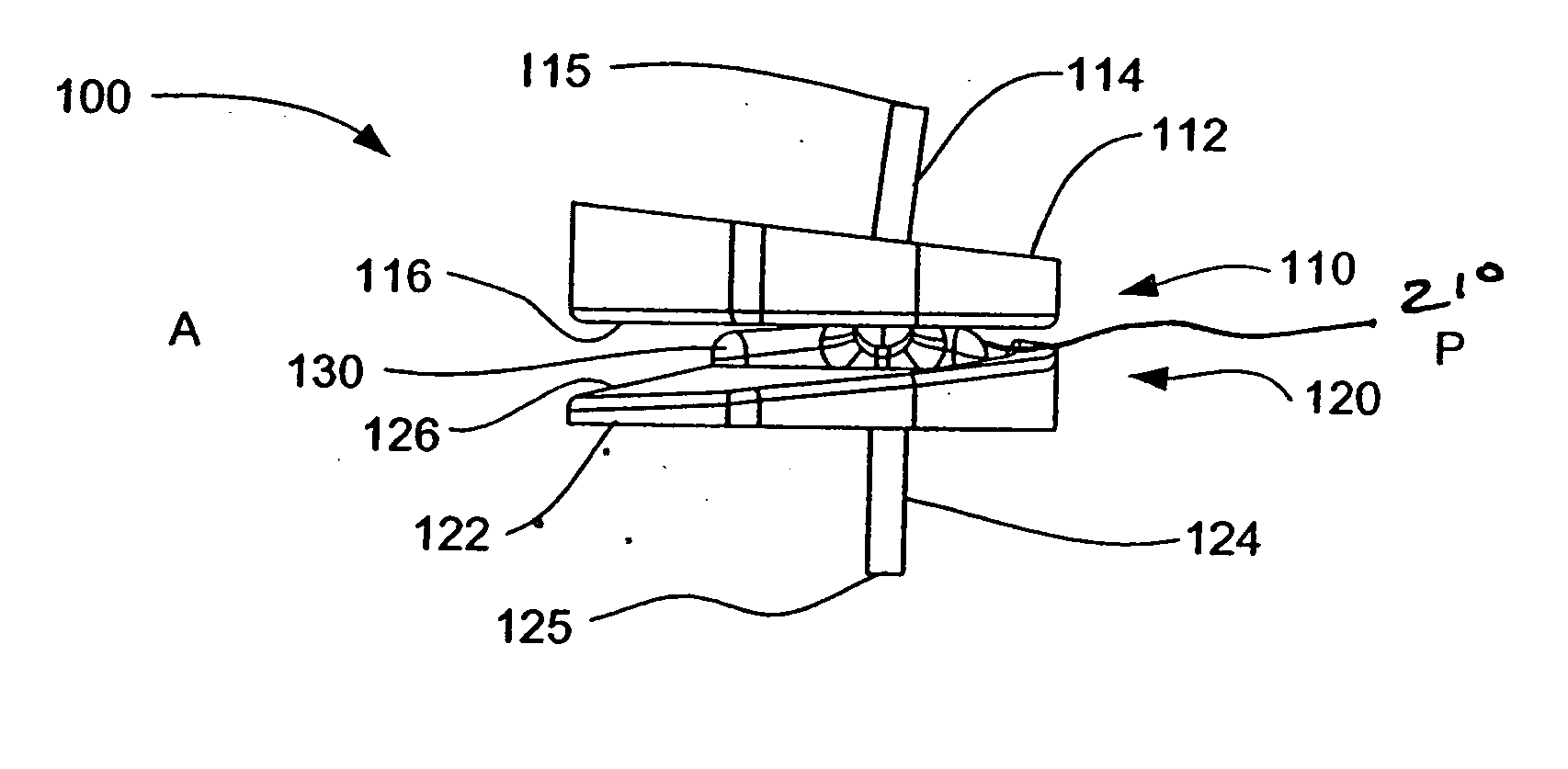
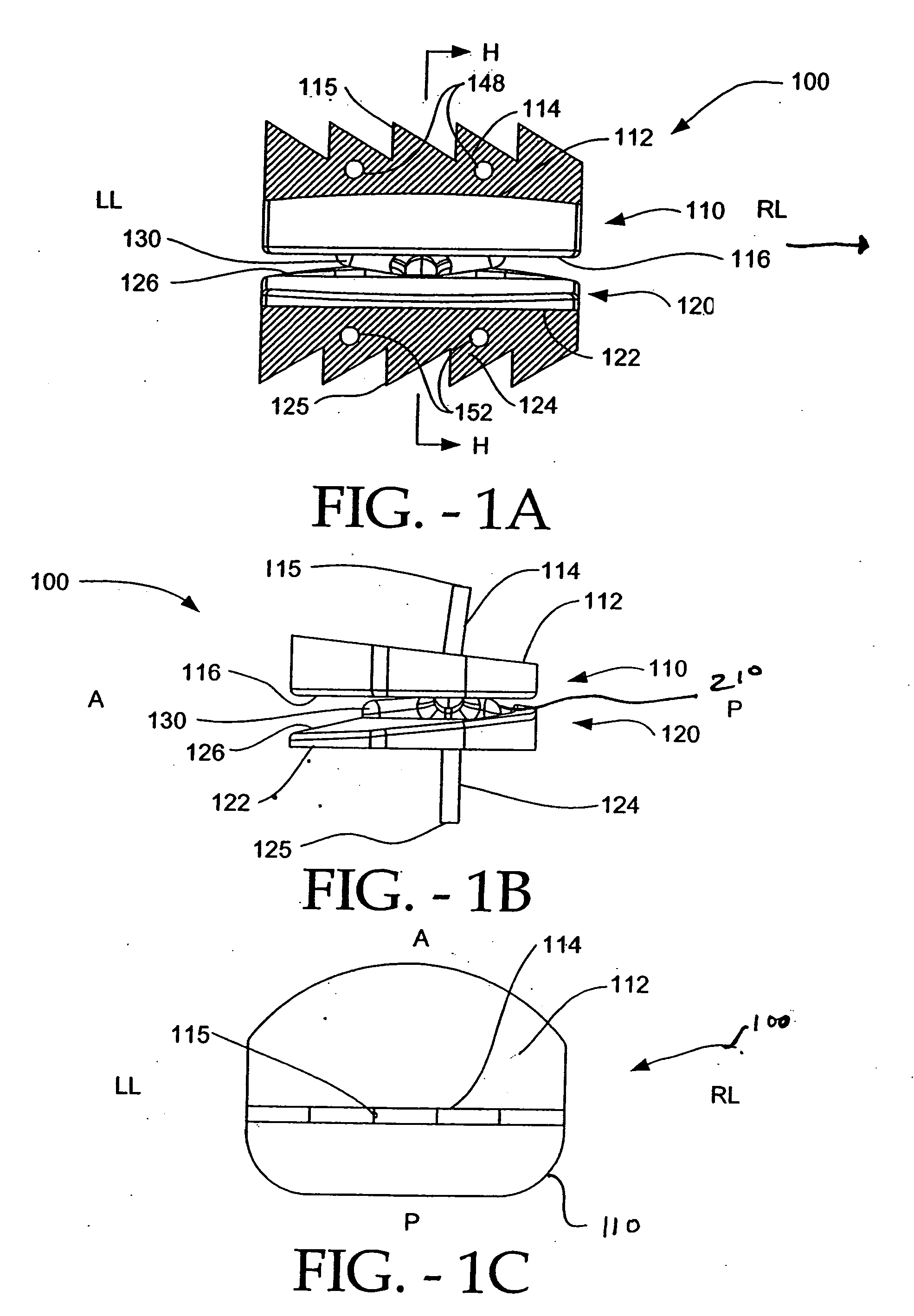
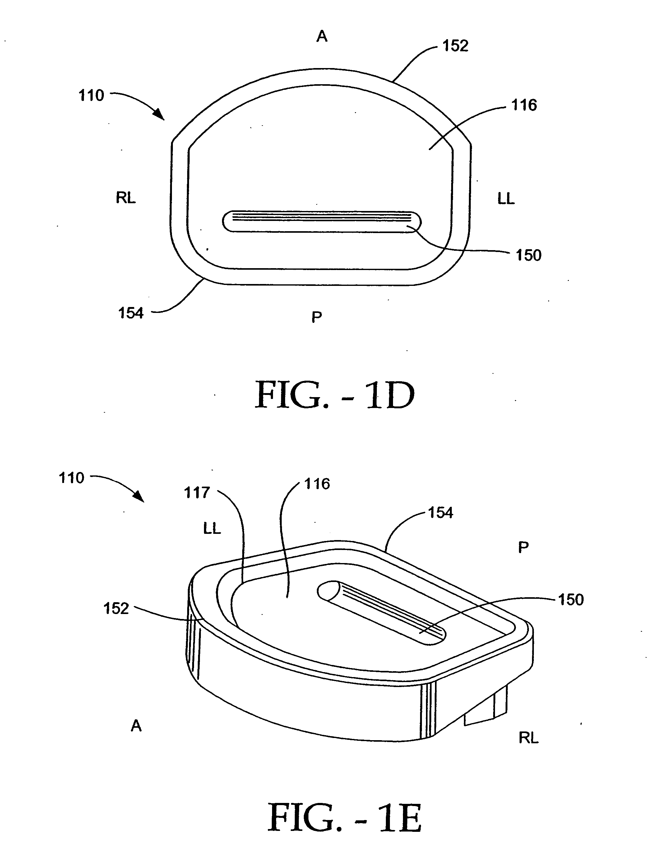
[0026]FIG. 1A shows a front view of an embodiment of the implant 100. The designations, “A” for anterior, “P” for posterior, “RL” for right lateral, and “LL” fo...


PUM

PropertyMeasurementUnit
Timeaaaaaaaaaa
Bending strengthaaaaaaaaaa

Abstract

The present invention is directed to an implant that can be placed between two adjacent vertebral bodies using a lateral insertion method. The implant is characterized as having a first end plate and a second end plate which a crossbar spacer therebetween. The crossbar spacer preferably fits within a channel on the inner surfaces of the first end plate and the second end plate, whereby the crossbar spacer allows pivots, twisting and/or rotational movement of the spine. The first end plate and the second end plate include a keel extending therefrom, whereby the keel traverses longitudinally between a first lateral side and a second opposed lateral side and is substantially perpendicular to the sagittal plane of the patient's spine.

Description

CLAIM OF PRIORITY [0001] This application claims priority under 35 USC 119 to co-pending U.S. Patent Applications No. 60 / 517,791, filed Nov. 5, 2003 and entitled “ARTIFICIAL VERTEBRAL DISK REPLACEMENT IMPLANT WITH CROSSBAR SPACER AND LATERAL IMPLANT METHOD,” (KLYCD-05008US2) and No. 60 / 517,973, filed Nov. 6, 2003 and entitled “ARTIFICIAL VERTEBRAL DISK REPLACEMENT IMPLANT WITH CROSSBAR SPACER AND LATERAL IMPLANT METHOD,” (KLYCD-05008US3) both of which are hereby incorporated by reference. CROSS-REFERENCE TO RELATED APPLICATIONS [0002] This application is related to U.S. Provisional Application No. 60 / 422,039, filed Oct. 29, 2002, entitled “ARTIFICIAL VERTEBRAL DISK REPLACEMENT IMPLANT WITH TRANSLATING PIVOT POINT AND METHOD,” U.S. patent application Ser. No. 10 / 684,668, filed Oct. 14, 2003, entitled “ARTIFICIAL VERTEBRAL DISK REPLACEMENT IMPLANT WITH CROSSBAR SPACER AND METHOD,” U.S. patent application Ser. No. 10 / 684,669, filed Oct. 14, 2003, entitled “ARTIFICIAL VERTEBRAL DISK REP...

Claims


Application Information

Patent Timeline
IPC IPC(8): A61F2/00A61F2/30A61F2/44
CPCA61F2/30771A61F2310/00976A61F2/4425A61F2002/30163A61F2002/30172A61F2002/30392A61F2002/30878A61F2002/30884A61F2002/30892A61F2002/30899A61F2002/443A61F2220/0025A61F2230/0028A61F2230/0052A61F2310/00017A61F2310/00023A61F2310/00029A61F2/30965A61F2002/30179
Inventor ZUCHERMAN, JAMES F.HSU, KEN Y.MITCHELL, STEVEN T.
Owner KYPHON
Why Eureka
Try Eureka