Sighting instrument for determining the mechanical axis of the femur

a technology of mechanical axis and femur, which is applied in the field of determining the mechanical axis of the femur, can solve the problems of increasing the surgical time between 20 and 30 minutes, lack of precision, and the traditional method used for many years, and achieves the effect of simple, fast and less costly

Active Publication Date: 2009-08-27
BREVEXCO S P R L
View PDF35 Cites 54 Cited by
  • Summary
  • Abstract
  • Description
  • Claims
  • Application Information

AI Technical Summary

Benefits of technology

[0018]The present invention allows determining in a simple fast and less costly manner the exact localization of the mechanical axis compared to the knee and, as a consequence, adjusting, with great precision, the positioning of the prosthesis compared to this axis. It allows, from another point of view, the avoidance of the need to introduce a metallic rod inside the femoral medullar cavity.

Problems solved by technology

The first method, used traditionally for many years, unfortunately lacks precision.
In fact, errors of angle measurement on the pre-surgical cliché (rotation errors etc.) can appear.
In addition, the introduction of the rod into the femur diaphysis has some disadvantages, as it destroys, to a certain degree, the diaphysis bone marrow and fat embolisms have been reported in the post-surgical stage, possibly connected to the introduction of this rod.
Nevertheless, this method needs, on the one hand, to use sophisticated and costly technical methods and, on the other, in order to put this method into place, it generally entails an increase in the surgical time evaluated between 20 and 30 minutes.

Method used


Image

  • Sighting instrument for determining the mechanical axis of the femur
  • Sighting instrument for determining the mechanical axis of the femur
  • Sighting instrument for determining the mechanical axis of the femur

Examples


Embodiment Construction

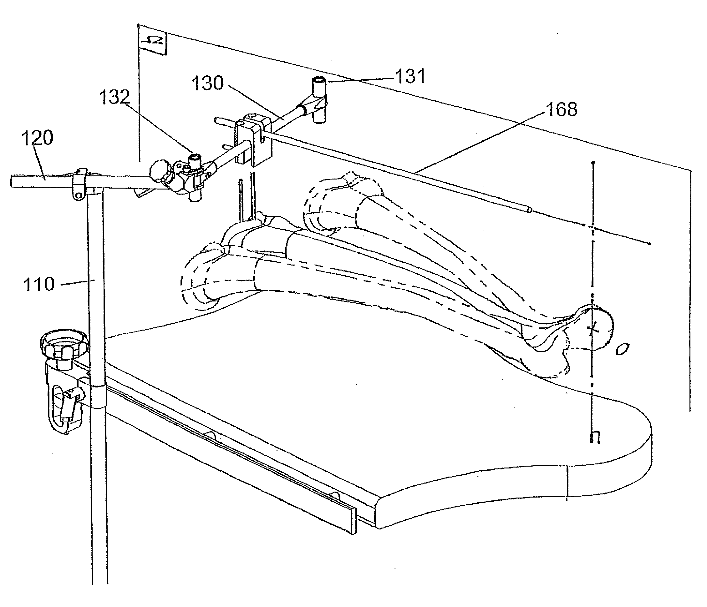
[0128]FIGS. 27 to 42 describe in a more detailed way the means of using the invention in the form of a construction of articulated bars 140 and 150 and of a sighting system 160.

[0129]For the sake of simplicity, it is considered that the main axis of the patient's body is aligned with the main axis of the surgery table 100 and the surgery table is strictly horizontal (or parallel relative to the ground). Thus, “vertical” means perpendicular to the surgery table and thus to the ground in the present case.

[0130]FIG. 27 illustrates the primary adjustment unit 140 made up of a vertical bar 110 and a clamp 190, in a isometric view. It is a rigid bar 110 being able to slide along the vertical axis (perpendicular relative to the surgery table or perpendicular to the ground considering the surgery table is strictly horizontal) in a vise assembly 90 that allows to adjust the position of the support relatively to the patient. Vise assembly 90 has a 91 that allows the blocking of the vertical t...


PUM


Abstract

A device for the determination of a plane containing the mechanical axis of the femur includes a mechanical member of articulated and or/sliding elements for the determination and memorization of two positions in space (F1 and F2) of the same point (F) of the knee, freely selected, when the knee is in position P1 and P2, relative to a referential system. These positions are obtained by rotation of the inferior limb from position P1 to position P2, about the centre of the femoral head. The orientation of an omega plan perpendicular to the frontal or sagittal plane containing the centre of the femoral head and the centre of the knee can be materialized by a rod contained in this plane, which rod is fixed perpendicularly and in the middle of the arm having at the ends two localization elements for points F1 and F2.

Description

[0001]The present invention mainly refers to a device and to a process that can help to determinate or estimate the orientation of the femoral mechanical axis.[0002]It is a well-known fact that a knee prosthesis has to be placed perpendicularly to the mechanical axis of the inferior limb. This axis goes through the rotational centre of the hip, the centre of the knee and the centre of the ankle.[0003]An arthroplasty of the knee thus requires the realization of bone cutting at the level of the distal part of the femur with the most precise possible orientation.PRIOR ART[0004]The classical method of achieving this objective consists of measuring on a large pre-surgical radiography of the inferior limb, the angle (alpha) between the diaphysis axis (a) of the femur (real) and the mechanical (virtual) axis (M)).[0005]At the moment of intervention, there is used the femoral diaphysis axis in order to introduce an in-guide rod allowing pulling on the cutting instruments with an angle equal...

Claims


Application Information

Patent Timeline
Patent Type & Authority Applications(United States)
IPC IPC(8): A61B19/00A61F5/00
CPCA61G13/0036A61B17/155
Inventor COLLETTE, MICHEL
Owner BREVEXCO S P R L
Why Eureka
Try Eureka