Projection optical system adjustment method, prediction method, evaluation method, adjustment method, exposure method and exposure apparatus, program, and device manufacturing method

a projection optical system and adjustment method technology, applied in the direction of microlithography exposure apparatus, printers, instruments, etc., can solve the problems of difficult adjustment, inability to adjust the line width difference, and inability to meet the requirements of so-called zernike sensitivity methods, etc., to achieve high integration, good yield, and good precision

Inactive Publication Date: 2005-02-03
NIKON CORP
View PDF20 Cites 113 Cited by
  • Summary
  • Abstract
  • Description
  • Claims
  • Application Information

AI Technical Summary

Benefits of technology

[0014] The second object of the present invention is to provide a prediction method in which the characteristics of the pattern images via the projection optical system can be predicted easily and with high precision.
[0111] In addition, in a lithographic process, by performing exposure using any one of the first to fourth exposure apparatus of the present invention, the pattern can be formed on the object with good precision, which allows highly integrated microdevices to be produced with good yield, which consequently leads to improving the productivity. Similarly, in the lithographic process, by performing exposure using any one of the first to fifth exposure methods of the present invention, the pattern can be formed on the object with good precision, which allows highly integrated microdevices to be produced with good yield, which consequently leads to improving the productivity. Accordingly, further from another aspect, the present invention can also be said to be a device manufacturing method that uses any one of the first to fourth exposure apparatus of the present invention, or it can be said to be a device manufacturing method that uses any one of the first to fifth exposure methods of the present invention.

Problems solved by technology

Therefore, when the measurement found that asymmetric aberration such as coma could not be measured, correction of the line width difference was difficult.
When it comes to evaluating line width variation, however, the so-called Zernike sensitivity method is not necessarily suitable.
Due to such circumstances, in the present state of affairs, there is no simple and solid judgment method regarding the line width difference of the images of the vertical line pattern and the horizontal line pattern, therefore, its adjustment is also difficult.

Method used


Image

  • Projection optical system adjustment method, prediction method, evaluation method, adjustment method, exposure method and exposure apparatus, program, and device manufacturing method
  • Projection optical system adjustment method, prediction method, evaluation method, adjustment method, exposure method and exposure apparatus, program, and device manufacturing method
  • Projection optical system adjustment method, prediction method, evaluation method, adjustment method, exposure method and exposure apparatus, program, and device manufacturing method

Examples


Embodiment Construction

[0147] An embodiment of the present invention is described below, referring to FIGS. 1 to 12.

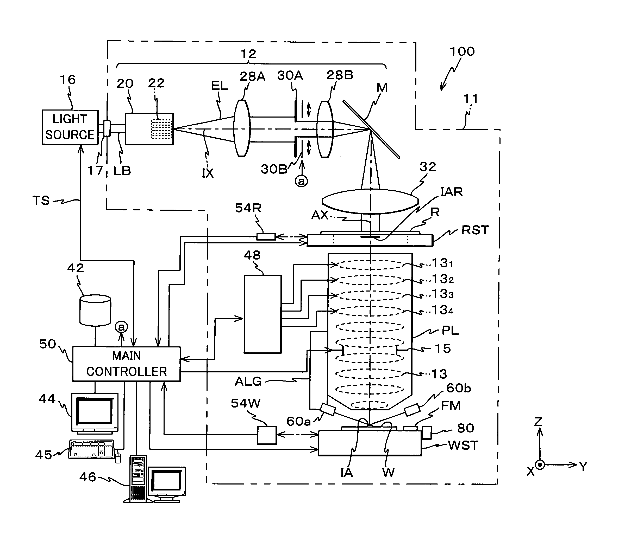
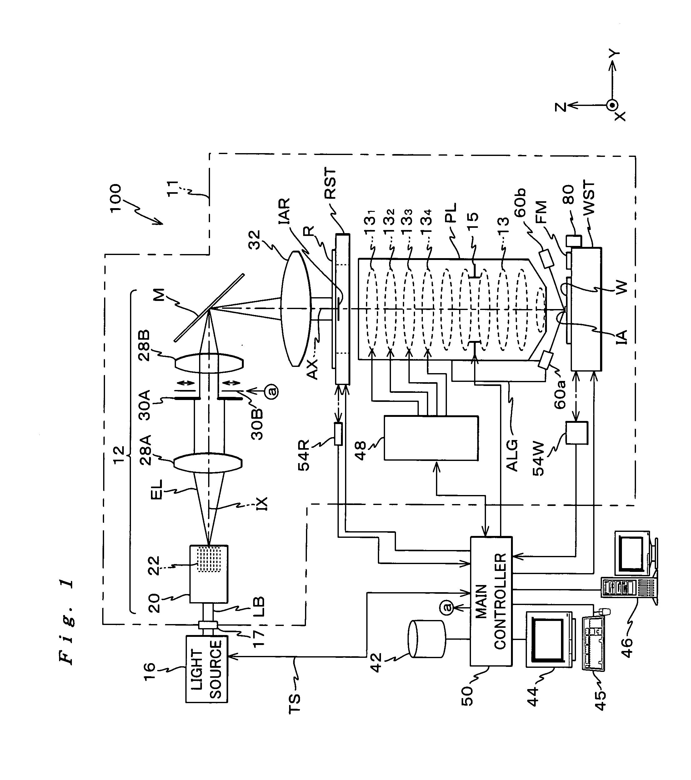
[0148]FIG. 1 shows an entire structure of an exposure apparatus 100 related to the embodiment. Exposure apparatus 100 is a reduction projection exposure apparatus (a so-called scanner) that uses a pulsed laser light source as its exposure light source (hereinafter referred to as ‘light source’).

[0149] Exposure apparatus 100 comprises: an illumination system made up of a light source 16 and an illumination optical system 12; a reticle stage RST serving as a mask stage that holds a reticle R serving as a mask, which is illuminated by an exposure illumination light EL serving as an energy beam from the illumination system; a projection optical system PL that projects exposure illumination light EL outgoing from reticle R onto a wafer W (on the image plane) serving as an object; a wafer stage WST that holds wafer W; a control system for the above parts, and the like.

[0150] As light source 16,...


PUM

PropertyMeasurementUnit
wavelengthaaaaaaaaaa
output wavelengthaaaaaaaaaa

Abstract

Wavefront aberration of a projection optical system is measured and information on the wavefront aberration is obtained (step 102). Furthermore, a pattern of a reticle is transferred onto a wafer via a projection optical system (steps 104 to 108). Then, the waver on which the pattern is transferred is developed, and line width measurement is performed on the resist image formed on the wafer and line width difference of images of a first line pattern extending in a predetermined direction and a second line pattern that is orthogonal to the first line pattern is measured (steps 112 to 118). And, according to a value of the 12th term of the Zernike polynomial, which is an expansion of the wavefront aberration, and the line width difference, the projection optical system is adjusted so that magnitude of the 9th term (a low order spherical aberration term) is controlled (steps 120 to 124).

Description

CROSS-REFERENCE TO RELATED APPLICATIONS [0001] This is a continuation of International Application PCT / JP2003 / 002375, with an international filing date of Feb. 28, 2003, the entire content of which being hereby incorporated herein by reference, which was not published in English.BACKGROUND OF THE INVENTION [0002] 1. Field of the Invention [0003] The present invention relates to projection optical system adjustment methods, prediction methods, evaluation methods, adjustment methods, exposure methods and exposure apparatus, programs, and device manufacturing methods, and more particularly to an adjustment method of a projection optical system that projects an image of a pattern on a first surface onto a second surface, a prediction method of characteristics of the image of the pattern via the projection optical system, an evaluation method for evaluating the characteristics of the image of the pattern that has undergone the prediction method, an adjustment method for adjusting the ima...

Claims


Application Information

Patent Timeline
Patent Type & Authority Applications(United States)
IPC IPC(8): G03F7/20
CPCG03F7/70258G03F7/70883G03F7/70625G03F7/706
Inventor HIRUKAWA, SHIGERUNAKASHIMA, TOSHIHARUHIGASHI, KENJI
Owner NIKON CORP
Why Eureka
Try Eureka