Spinous process implant spacer and method of use therefor

a technology of implant spacer and spinous process, which is applied in the field of spacer, can solve the problems of lumbar spinal canal stenosis, unfavorable unilateral implant insertion, and decompression of nerve structure, and achieve the effect of easy implant insertion

Inactive Publication Date: 2010-05-27
ROEBLING CHRISTIAN +1
View PDF1 Cites 60 Cited by
  • Summary
  • Abstract
  • Description
  • Claims
  • Application Information

AI Technical Summary

Benefits of technology

[0012]An aspect of the present invention is to provide a spinous process impl

Problems solved by technology

Degeneration of the vertebral column, which occurs particularly with increasing age, frequently leads to lumbar spinal canal stenosis.
In severe cases, distraction of the spine causes a decompression of the nerve

Method used


Image

  • Spinous process implant spacer and method of use therefor
  • Spinous process implant spacer and method of use therefor
  • Spinous process implant spacer and method of use therefor

Examples


first embodiment

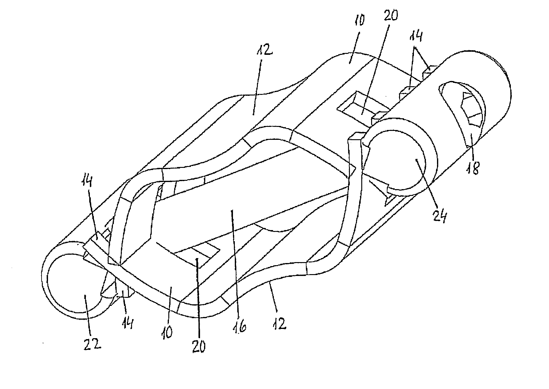
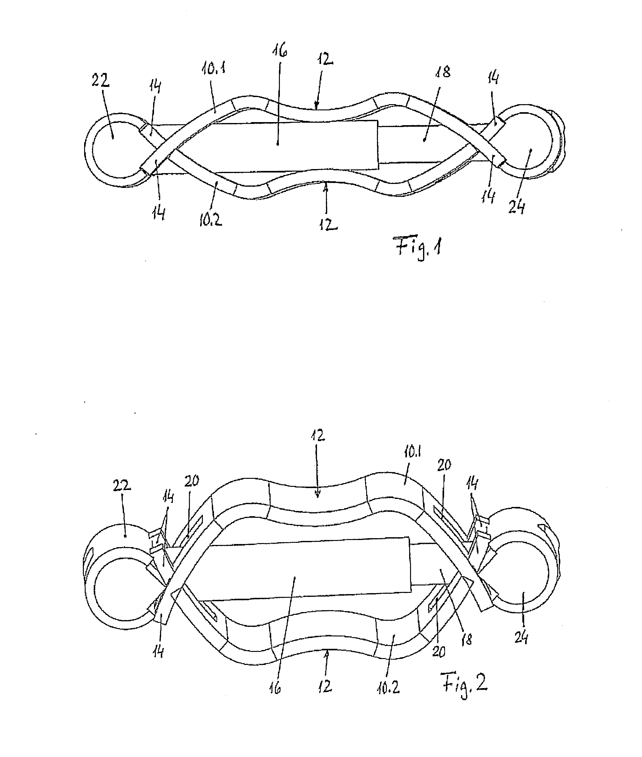
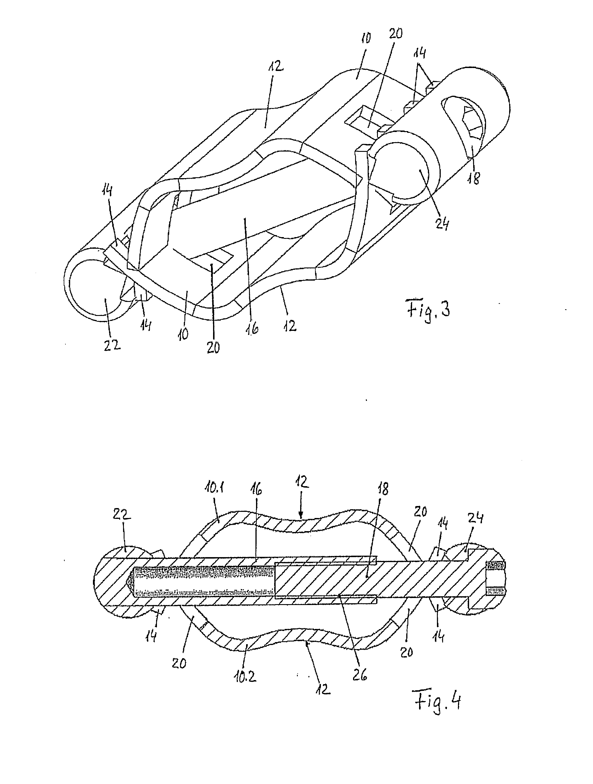
[0032]FIGS. 1-4 show the spinous process implant. The implant presents upper and lower support means that are designed as a spring leaf 10. The upper spring leaf 10.1 and the lower spring leaf 10.2 here are parts with identical shape that, however, are arranged with mutual twisting by 180° about the longitudinal middle axis of the implant. The spring leaves 10 have the shape of a longitudinally stretched, flat band that is shape elastic, i.e., it maintains its shape, although it is deformable when exposed to a relatively strong elastic resetting force. The spring leaves 10 are manufactured for this purpose from an appropriate biocompatible material, for example, from a metal, particularly a titanium alloy, or from an appropriate plastic, for example PEEK. The spring leaves 10 present, for example, a length of 15-30 mm, preferably 20-25 mm, a width of 4-8 mm, and a thickness of 0.8-1.2 mm.

[0033]The spring leaves 10 form a convex bulge, upward or downward, in their longitudinal direct...

second embodiment

[0038]FIGS. 5-9 represent the spinous process implant.

[0039]In this embodiment, the support means are designed as support plates 32. On the upper side, a left support plate 32.1 and a right support plate 32.2 are provided, and, accordingly, on the lower side, a left support plate 32.3 and a right support plate 32.4 are provided. The support plates 32.1, 32.2, 32.3 and 32.4 all have the same shape. The support plates 32 consist of an appropriate biocompatible, dimensionally stable material, for example, metal, particularly a titanium alloy or preferably an appropriate plastic, particularly PEEK. The fact that the shape of the support plates 32.1, 32.2, 32.3 and 32.4 is the same is advantageous with regard to the manufacturing costs.

[0040]The support plates 32 present the shape of a plate which is stretched in the longitudinal direction, with a length of approximately 15-30 mm, and a width of approximately 4-8 mm. The thickness of the material is approximately 1-2 mm. The support plat...


PUM


Abstract

A spinous process implant, and a method therefor can be positioned with its longitudinal axis substantially perpendicular to the median sagittal plane of the patient, between an upper and an adjacent lower spinous process. The implant comprises, as spacers, upper support means, and lower support means, which, in each case, are applied with a recess saddle against the upper or lower spinous process. The support means can be spread apart in each case by means of clamping means, which are arranged between the support means in the longitudinal direction.

Description

CROSS REFERENCE TO RELATED APPLICATIONS[0001]This application is related to, and claims priority from, European Patent Application Serial No. 08 020 138.7, filed Nov. 19, 2008, the entire contents of which is incorporated herein fully by reference.BACKGROUND OF THE INVENTION[0002]1. Field of the Invention[0003]The present invention relates to a spacer for facilitating a spinous process implant. More specifically, the present invention relates to a spinous process implant and spacer that can be implanted easily and is usable in many anatomical situations[0004]2. Description of the Related Art[0005]Degeneration of the vertebral column, which occurs particularly with increasing age, frequently leads to lumbar spinal canal stenosis. This is a narrowing of the spinal canal and of the intervertebral foramina (foramina intervertebralia), generally as a consequence of spinal disk degeneration. Typical symptoms are nerve pains in the back and in the legs, and in severe cases paralysis sympto...

Claims


Application Information

Patent Timeline
IPC IPC(8): A61B17/70A61B17/88
CPCA61B17/7071A61B17/7062
Inventor ROEBLING, CHRISTIANACKERMANN, ROLF
Owner ROEBLING CHRISTIAN
Why Eureka
Try Eureka