Implant

Inactive Publication Date: 2006-11-02
WARSAW ORTHOPEDIC INC
View PDF34 Cites 181 Cited by
  • Summary
  • Abstract
  • Description
  • Claims
  • Application Information

AI Technical Summary

Benefits of technology

[0011] Embodiments of the present invention relate to an implant, such as a nucleus implant or replacement that, on the one hand, may be configured to have a sufficiently small cross-section to be implanted by a minimally invasive procedure and, on the other hand, may be configured to have a sufficiently large effective size and appropriate shape to conform to the natural size and shape of the nuclear cavity (or other space) once implanted. In the case of nucleus implants, such conformity serves to maintain natural disc height, or spacing between vertebrae, which in turn subserves the basic functions of the natural disc nucleus, permitting motion while providing

Problems solved by technology

Intervertebral discs may be displaced or damaged due to, for example, trauma or disease.
Intervertebral discs may also deteriorate due to the normal aging process.
The reduction of the disc height, or spacing between adjacent vertebrae, leads to instability of the spine, decreased mobility and pain.
However, removal of the damaged or unhealthy disc may allow the disc space to collapse, which would lead to instability of the spine, abnormal joint mechanics and nerve damage, as well as severe pain.
While a certain degree of success with these devices has been achieved, full motion is typically never regained after such vertebral fusions.
Many of these implants are complicated, bulky devices made of a combination of metallic and elastomeric components.
Thus, implantation of such devices requires an invasive surgical procedure,

Method used


Image

  • Implant
  • Implant
  • Implant

Examples


Embodiment Construction

[0029] While the present invention is described and illustrated in detail in the following description and accompanying drawings, the same is to be considered as illustrative and not restrictive in character, it being understood that only certain embodiments are discussed and shown herein. The invention is intended to encompass such modifications, equivalent arrangements, and applications of the principles of the invention as would be understood by those of ordinary skill in the pertinent arts to fall within the spirit and scope of the invention.

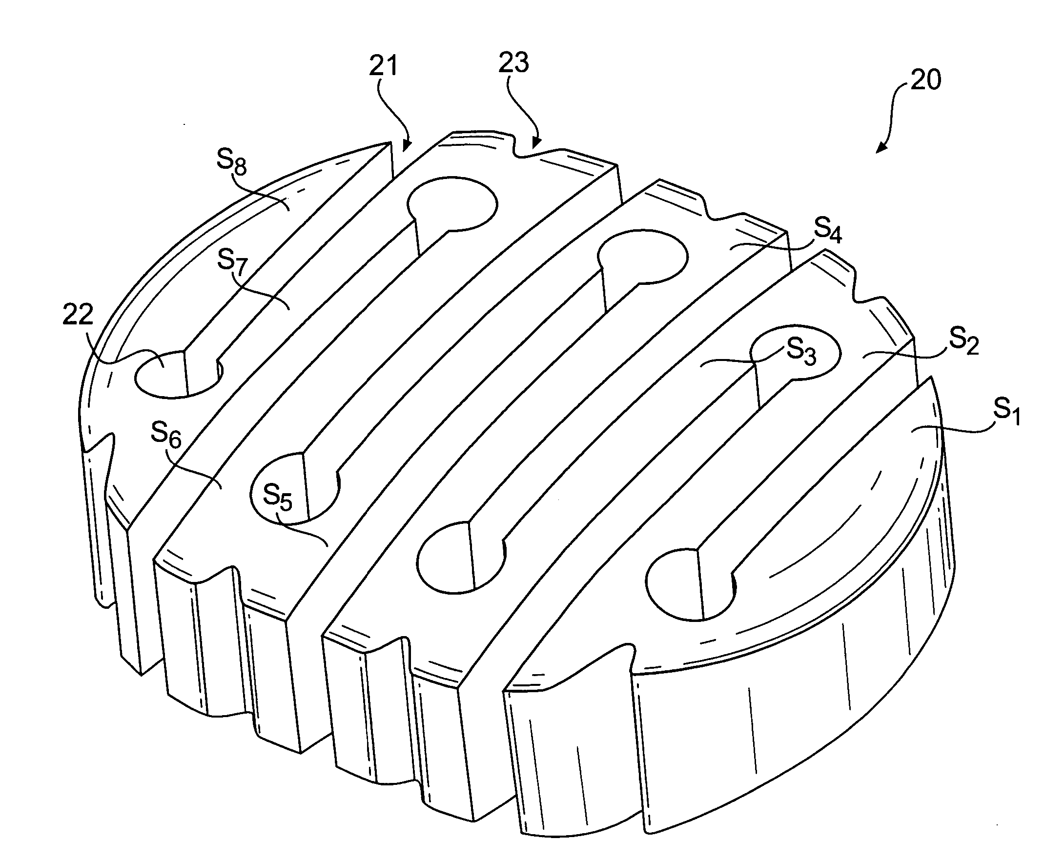
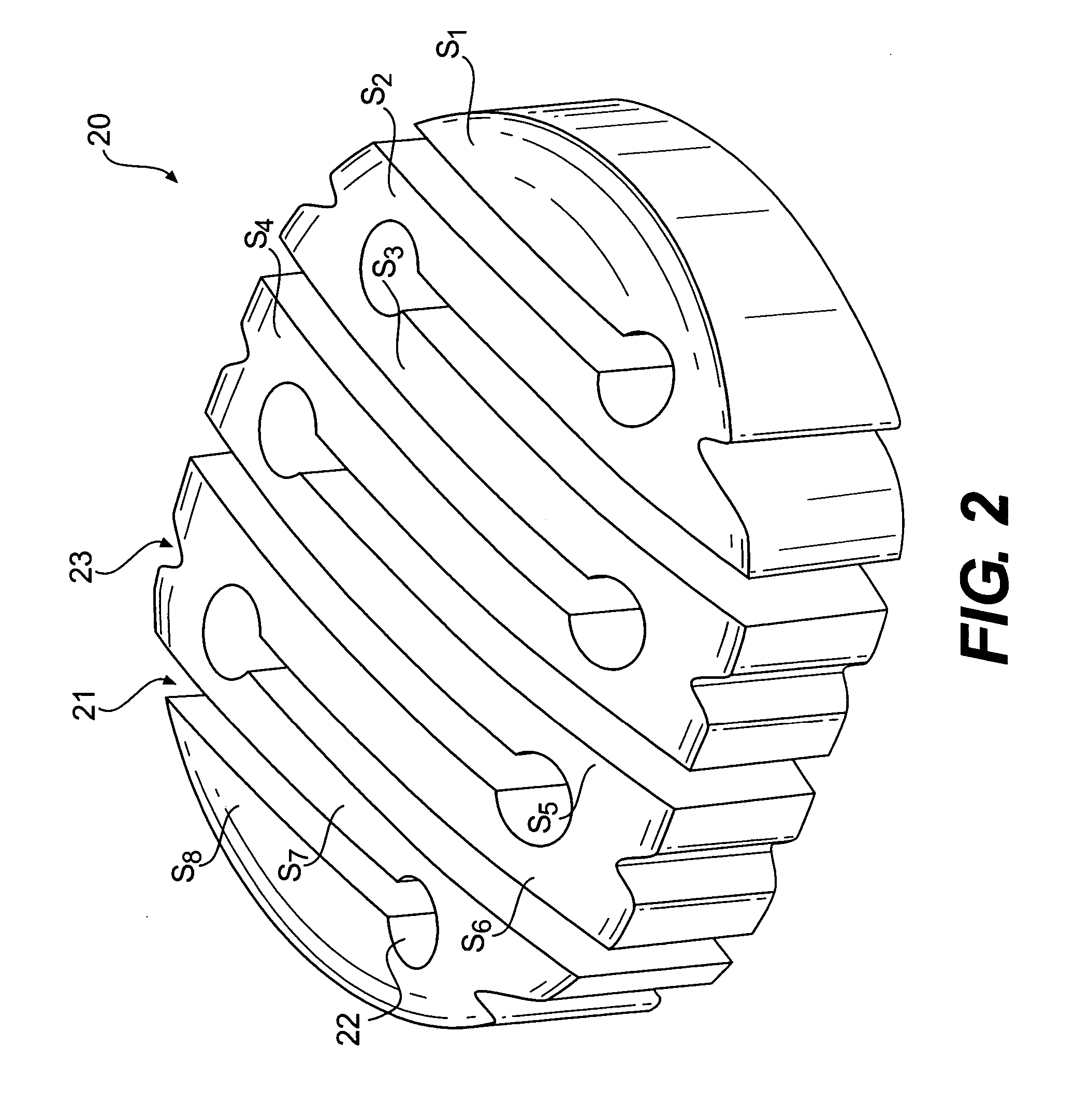
[0030] The structure and operation of a nucleus implant or replacement according to a first embodiment of the present invention will be explained with reference to the accompanying drawings. FIGS. 2, 3A-3C and 4A-4D show an implant 20 in a folded state, FIG. 5 shows the implant 20 in the process of being folded, and FIGS. 6A and 6B show the implant 20 in an unfolded state. Of these figures, FIGS. 4A-4D show the implant 20 in vivo, i.e., imp...


PUM

PropertyMeasurementUnit
Widthaaaaaaaaaa
Lengthaaaaaaaaaa
Shape memory effectaaaaaaaaaa

Abstract

An intervertebral disc nucleus replacement is provided that is configurable into a first configuration to be assumed while the replacement is implanted in the nuclear cavity and a second configuration to be assumed during the procedure of inserting the replacement into the nuclear cavity. The first configuration may have an accordion-like structure formed by a plurality of sections folded in an alternating, zigzag-like manner, and may be sized and shaped to conform to the nuclear cavity. The second configuration may be formed by straightening the plurality of folded sections into an unfolded, elongated, linear member, thereby affording a smaller effective cross-section. The nucleus replacement may be made of an elastic material having shape memory and may be formed so that the first configuration is an unmanipulated or relaxed configuration and the second configuration is a manipulated or unrelaxed configuration.

Description

BACKGROUND OF THE INVENTION [0001] 1. Field of the Invention [0002] Embodiments of the present invention relate to an implant and, in particular, to an implant suitable at least for use as an intervertebral disc nucleus implant or replacement. [0003] 2. Description of the Related Art [0004] In a normal human being or other vertebrate animal, intervertebral discs serve to dynamically stabilize the spine and to distribute forces between vertebral bodies. Referring to FIG. 1A, an intervertebral disc 10 includes a gelatinous nucleus pulposus 11, and an annulus fibrosis 12. The disc 10 is located between two vertebral end plates 16 (see FIGS. 4B and 4D). The nucleus pulposus 11 is laterally surrounded and confined by the annulus fibrosis 12. Both the nucleus pulposus 11 and the annulus fibrosis 12 are surrounded and confined above and below by the respective vertebral end plates 16. (For simplicity, the nucleus pulposus and the annulus fibrosis will hereinafter generally be referred to a...

Claims


Application Information

Patent Timeline
IPC IPC(8): A61F2/44A61F2/02
CPCA61F2/442A61F2250/0098A61F2002/2817A61F2002/30062A61F2002/3008A61F2002/30092A61F2002/30596A61F2002/30598A61F2002/30677A61F2002/30919A61F2002/4415A61F2002/444A61F2210/0004A61F2210/0014A61F2/4611A61F2002/30594
Inventor FRANCIS, TOM J.
Owner WARSAW ORTHOPEDIC INC
Why Eureka
Try Eureka