Supercharge Your Innovation With Domain-Expert AI Agents!

Cooling system for the cooling of tool pieces

a technology for cooling system and tool parts, applied in the field of cooling system for tool parts, can solve the problems of disadvantageous clogging, reduced heat transfer between the fluid inlet and the fluid outlet, and considerable disadvantages of the known cooling system

Active Publication Date: 2009-04-14
MHT MOLD & HOTRUNNER TECH
View PDF12 Cites 6 Cited by
  • Summary
  • Abstract
  • Description
  • Claims
  • Application Information

AI Technical Summary

Benefits of technology

This configuration enhances cooling efficiency by increasing fluid turbulence, improving heat transfer, and minimizing the risk of line clogging, allowing for more effective cooling of a larger number of tool parts within a compact machine.

Problems solved by technology

The known cooling system suffers from considerable disadvantages, however.
At the same time, if the core plate contains the connector lines it may disadvantageously clog up, because impurities settle and are not washed away, as a result of the slow flow and the low pressure in the fluid lines.
The heat transfer between the fluid inlet and the fluid outlet is reduced, a further disadvantage.

Method used


Image

  • Cooling system for the cooling of tool pieces
  • Cooling system for the cooling of tool pieces
  • Cooling system for the cooling of tool pieces

Examples


Embodiment Construction

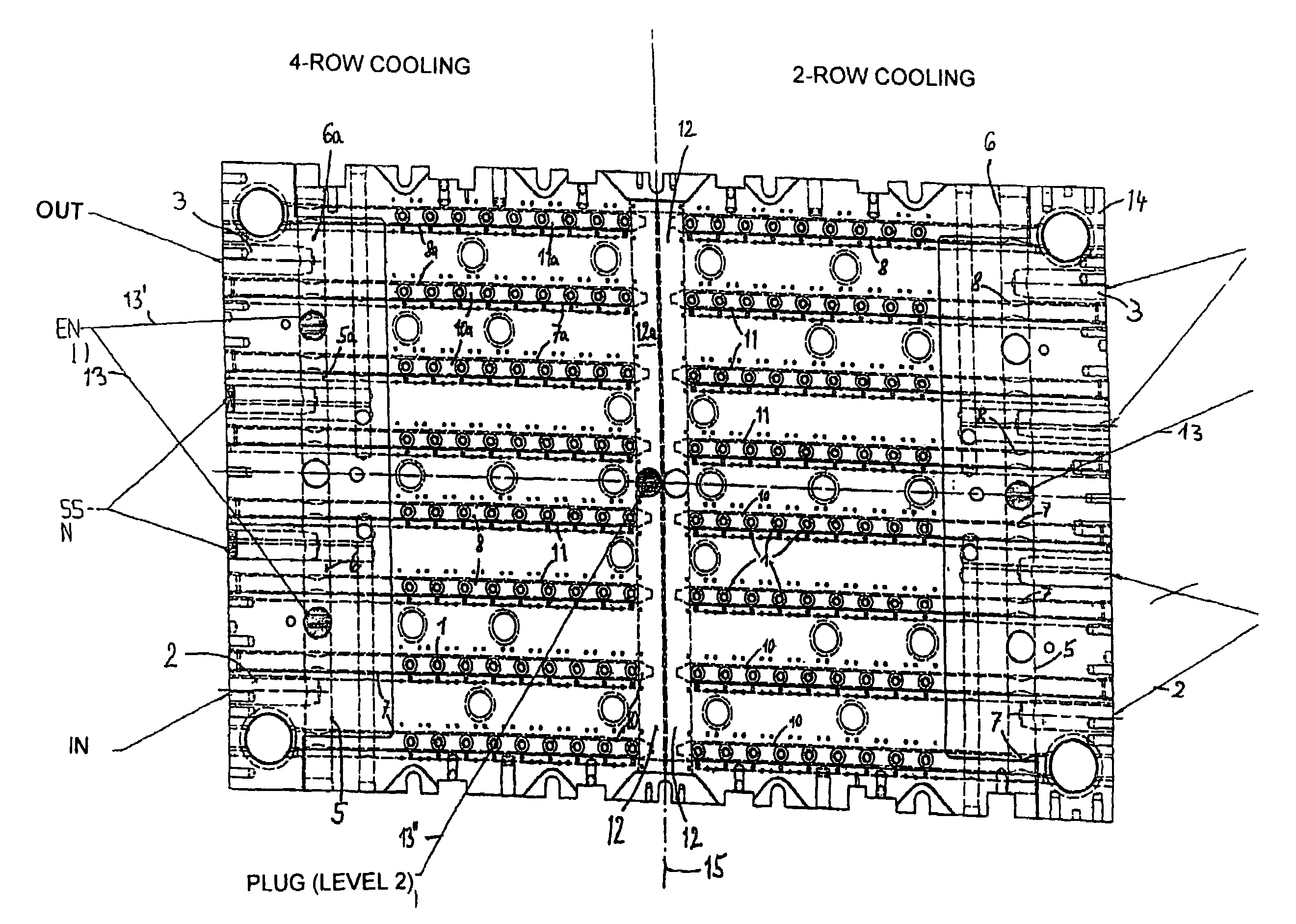
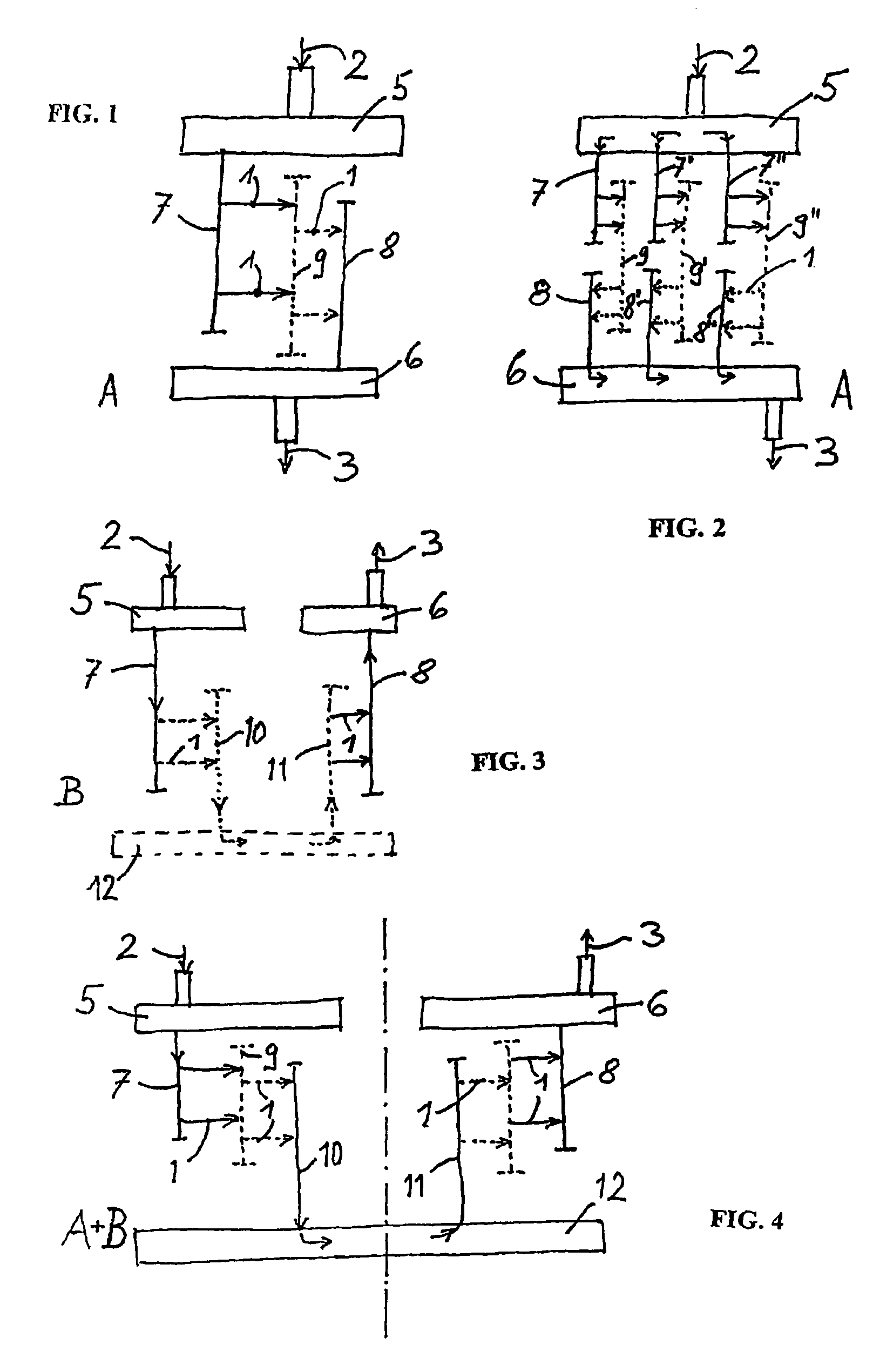
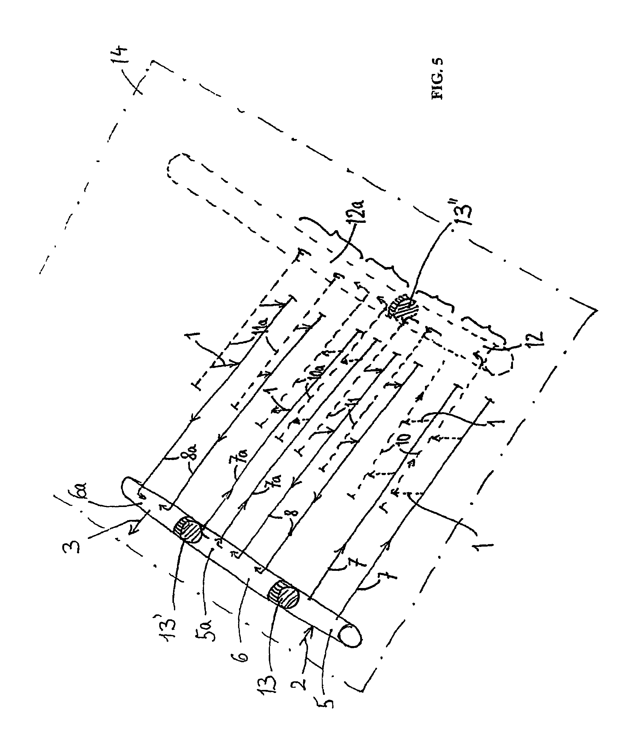
[0019]In accordance with the invention, the term tool parts is used to mean an element through which cooling fluid flows, for example a tube or a core. The invention can also be applied with those tool parts or cores which are secured to a plate, for example the cores on a core plate. Here too, water is presumed to be the cooling fluid and is guided from an inlet through connector lines to an outlet. The connector lines provide the connection to the tool parts. In the case of the known cooling systems, the fluid flows out of the inlet through a connector line and then through the tool part or, in practice, usually through a series of tool parts, to another connector line and from there directly to the outlet. The one connector line is connected to the fluid inlet and the other to the fluid outlet. The tool parts are located between the one and the other connector line.

[0020]If, in accordance with the teaching of the invention, a connector line (which could also be designated an inte...


PUM

PropertyMeasurementUnit
surface areaaaaaaaaaaa
diameteraaaaaaaaaa
surface areaaaaaaaaaaa

Abstract

A cooling system for cooling tool parts. The system includes at least one base system including a fluid guided from a fluid inlet through connector lines to a fluid outlet. The tool parts are connected in the direction of through-flow between at least one connector line connected to the fluid inlet and at least one connected to the fluid outlet, wherein, between the at least one connector line connected to the fluid inlet and the at least one connector line connected to the fluid outlet, at least one additional connector line and tool parts which are in flow communication therewith are placed in between such that, on its flow path, the fluid flows through at least two tool parts one after the other.

Description

BACKGROUND OF THE INVENTION[0001]The invention relates to a cooling system for cooling tool parts with the aid of a fluid guided from a fluid inlet through connector lines to a fluid outlet, the tool parts being connected in the direction of through-flow between at least one connector line connected to the fluid inlet and at least one connected to the fluid outlet.[0002]EP-B2-0 283 644 discloses an injection moulding machine which has an injection moulding plate with cavities and a core plate with projecting cores, the number of cores corresponding to the number of cavities. As the moulding plate on the one hand and the core plate on the other move towards one another, the cores engage in the cavities and, in the closed position, form between them the injection mould cavity in which a hollow parison made of synthetic material is shaped by an injection moulding procedure. These parisons, which are in particular made of PET, are later used to make the known PET bottles by blow mouldin...

Claims


Application Information

Patent Timeline
Patent Type & Authority Patents(United States)
IPC IPC(8): B29C45/73B29C45/72B29C49/64
CPCB29C45/7207B29C45/73B29C49/6427B29C2033/042B29C2045/725
Inventor LAUSENHAMMER, MANFREDWAGNER, CHRISTIAN
Owner MHT MOLD & HOTRUNNER TECH
Features
  • R&D
  • Intellectual Property
  • Life Sciences
  • Materials
  • Tech Scout
  • Unparalleled Data Quality
  • Higher Quality Content
  • 60% Fewer Hallucinations
Learn More