Conveyor system with moveable drop point

a conveyor system and drop point technology, applied in the field of conveyor systems, can solve the problems of slow sausage production, difficult and time-consuming, and changing the spacing,

Active Publication Date: 2009-04-21
STORK TOWNSEND BV
View PDF13 Cites 14 Cited by
  • Summary
  • Abstract
  • Description
  • Claims
  • Application Information

AI Technical Summary

Benefits of technology

The patent describes a conveyor system that moves sausage strands from a loading station to an unload station. The system includes a frame with an operating platform and a moveable carriage that has a sprocket/pulley and an end turn or drop point sprocket/pulley. A continuous conveyor chain with hooks is mounted about the sprockets/pulleys. The system is designed to unload the sausage strands onto a smoke stick as the carriage moves back to the start position. The technical effect of this system is to provide a more efficient and automated process for producing sausage links.

Problems solved by technology

The patent text describes a conveyor system for transporting sausage loops to a smoke stick for further processing. The technical problem addressed by the invention is the need for a conveyor system that can easily adjust the spacing between loops, reduce the time required for removal and replacement of the smoke stick, and increase efficiency in sausage production.

Method used


Image

  • Conveyor system with moveable drop point
  • Conveyor system with moveable drop point

Examples


Embodiment Construction

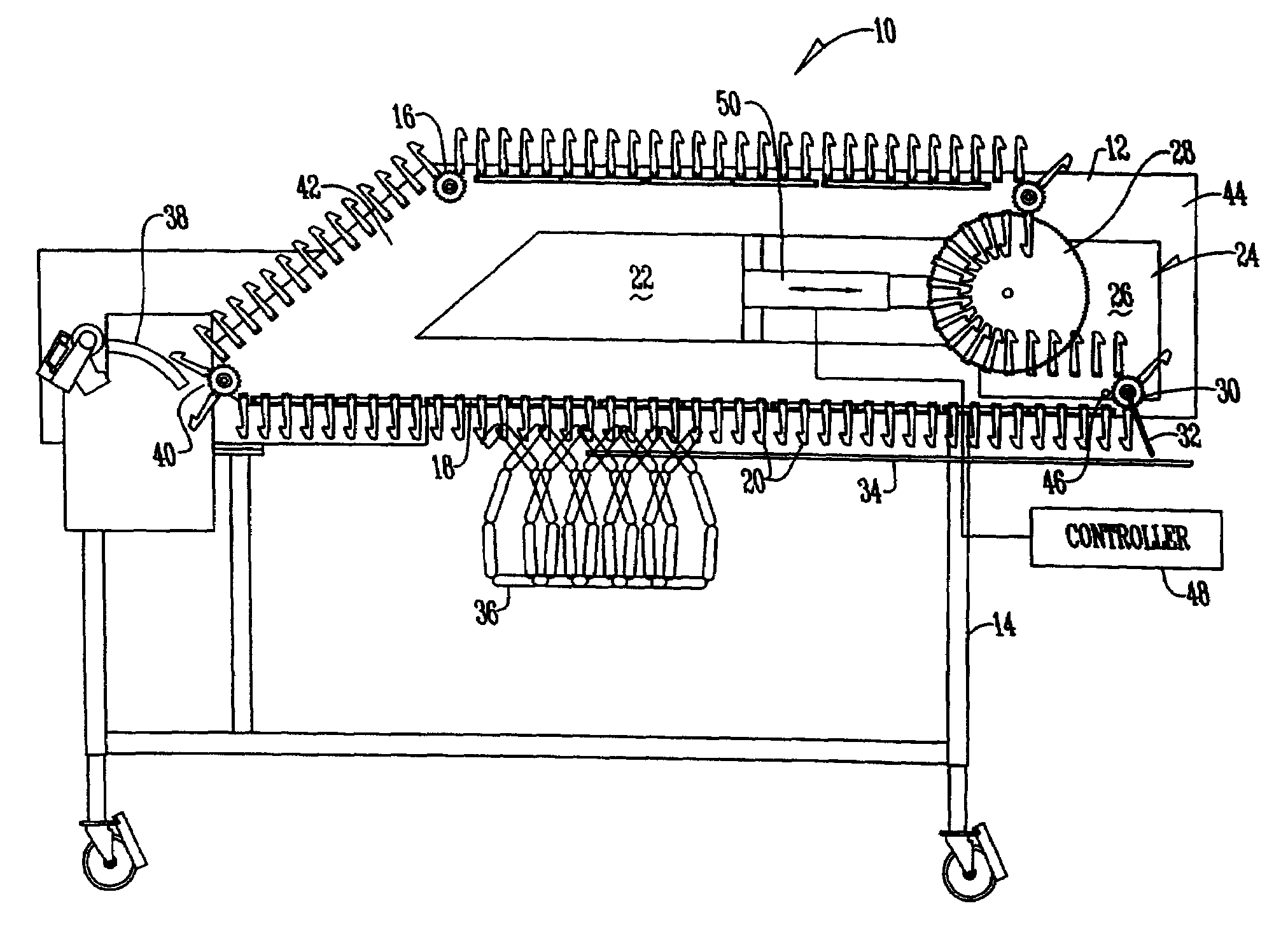
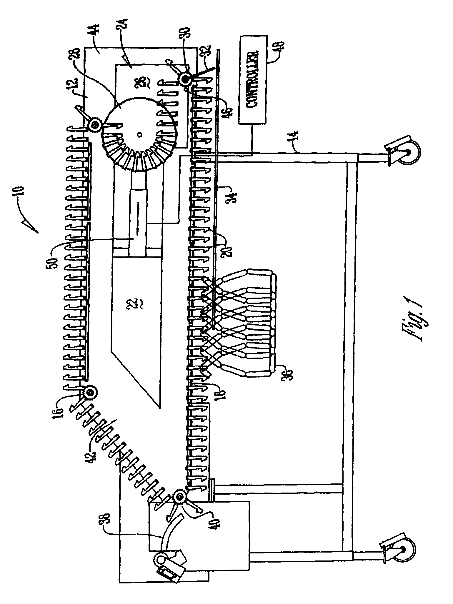
[0010]The conveyor assembly 10 has an operating platform 12 supported by a frame 14. The operating platform 12 typically is positioned in a vertical plane, but may also be supported by the frame 14 in a horizontal plane. A plurality of rotational members 16 such as sprockets, pulleys, and the like are attached to the platform 12 adjacent the outer perimeter of the platform 12. A continuous conveying chain or belt 18 is mounted to sprockets 16. A plurality of hooks 20 are secured to the chain 18 in any conventional manner. One of the sprockets 16, typically at the loading point 40 is driven by an electric motor to move chain 18 and hooks 20 past the loading point 40. Slidably mounted in opening 22 of the platform 12 is carriage 24. Carriage 24 has a plate 26 upon which a first sprocket 28 is rotatably mounted. A second end turn or (drop point) sprocket 30 is also mounted to plate 26. In one embodiment, a wiper 32 is mounted to the drop point sprocket 30 or alternatively to plate 26. ...


PUM


Abstract

A conveyor system for transporting a strand of sausage having a carriage slidably mounted to an operating platform where the carriage has an end turn sprocket where the strand is dropped onto a smoke stick and the carriage moves to drop the strand along the length of the smoke stick.

Description


Claims


Application Information

Patent Timeline
Owner STORK TOWNSEND BV
Why Eureka
Try Eureka