
Prosthetic foot with an adjustable ankle and method

a technology of prosthetic feet and ankles, applied in the field of prosthetic feet with adjustable ankles, can solve the problems that the development of functional and natural artificial feet has been limited by material and imagination

Inactive Publication Date: 2009-04-21
FREEDOM INNOVATIONS INC
View PDF151 Cites 92 Cited by
  • Summary
  • Abstract
  • Description
  • Claims
  • Application Information

AI Technical Summary

Benefits of technology

"The invention is a prosthetic foot with an adjustable ankle that can be used with different shoes, such as ones with different heel heights. The ankle is adjusted through a movable coupling and an actuator, and sensors and a controller are used to process the sensory information and engage the actuator accordingly. The lower portion of the foot moves in two directions simultaneously, and can be adjusted to different positions. The foot also has a tractor bolt and a level sensor to automatically adjust the ankle and make the foot level or vertically oriented. Overall, the invention provides a more natural feel and use for prosthetic feet."

Problems solved by technology

With respect to prosthetic feet, the development of a functional and natural artificial foot has been limited only by material and imagination.
Few designs consider the use of the foot with different shoes, such as different heel heights.

Method used


Image

  • Prosthetic foot with an adjustable ankle and method
  • Prosthetic foot with an adjustable ankle and method
  • Prosthetic foot with an adjustable ankle and method

Examples


Embodiment Construction

[0035]Reference will now be made to the exemplary embodiments illustrated in the drawings, and specific language will be used herein to describe the same. It will nevertheless be understood that no limitation of the scope of the invention is thereby intended. Alterations and further modifications of the inventive features illustrated herein, and additional applications of the principles of the inventions as illustrated herein, which would occur to one skilled in the relevant art and having possession of this disclosure, are to be considered within the scope of the invention.

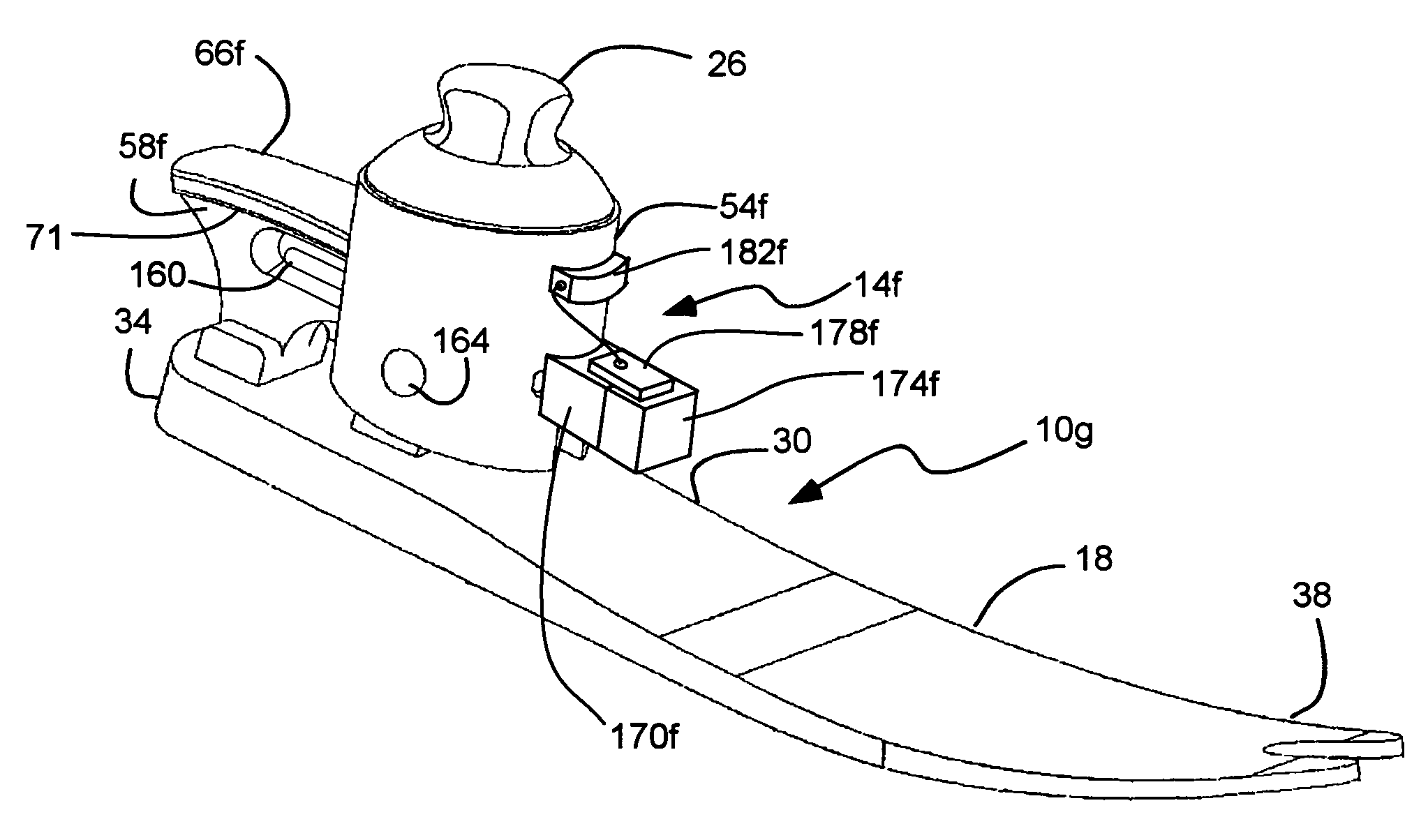
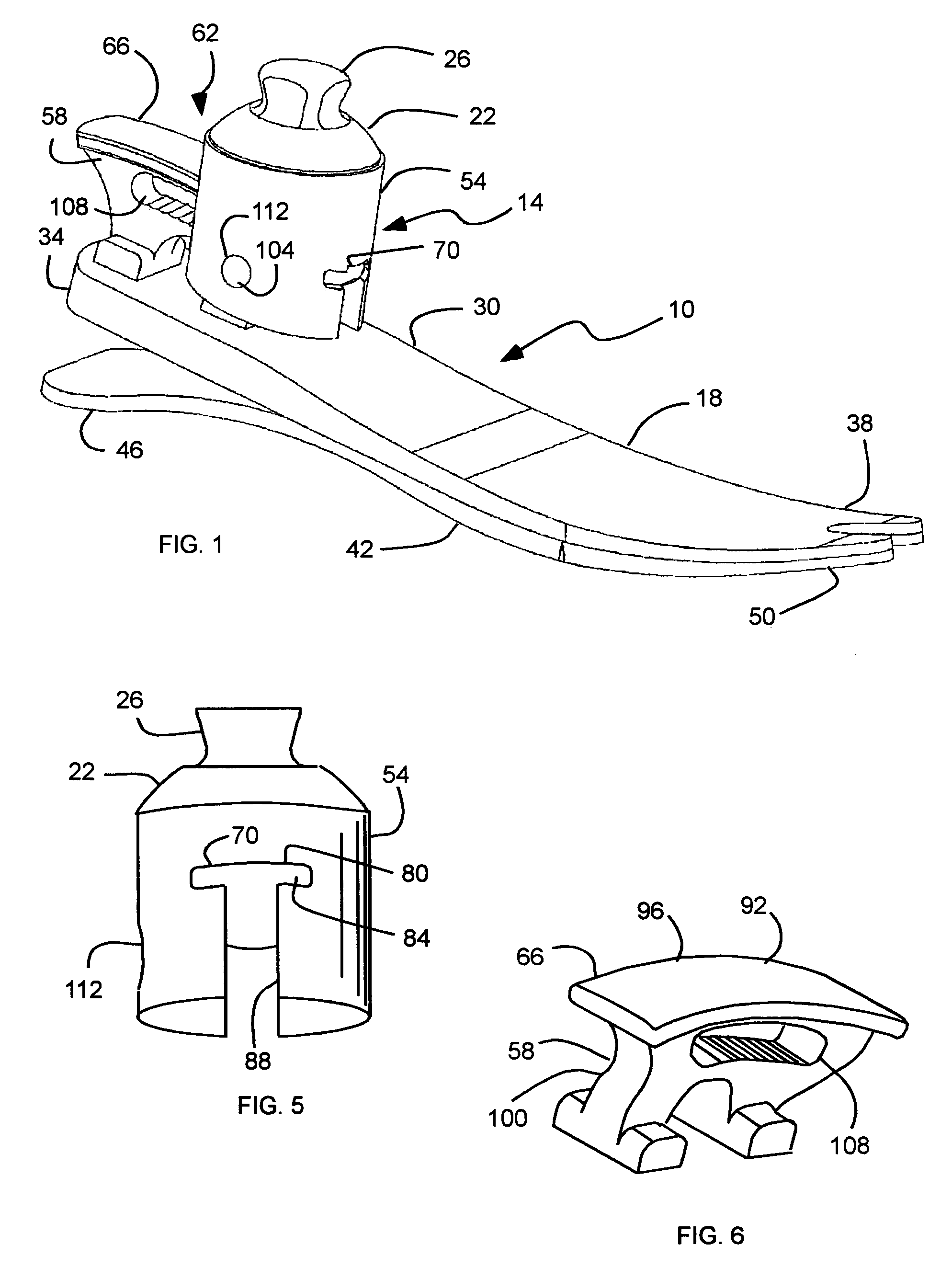
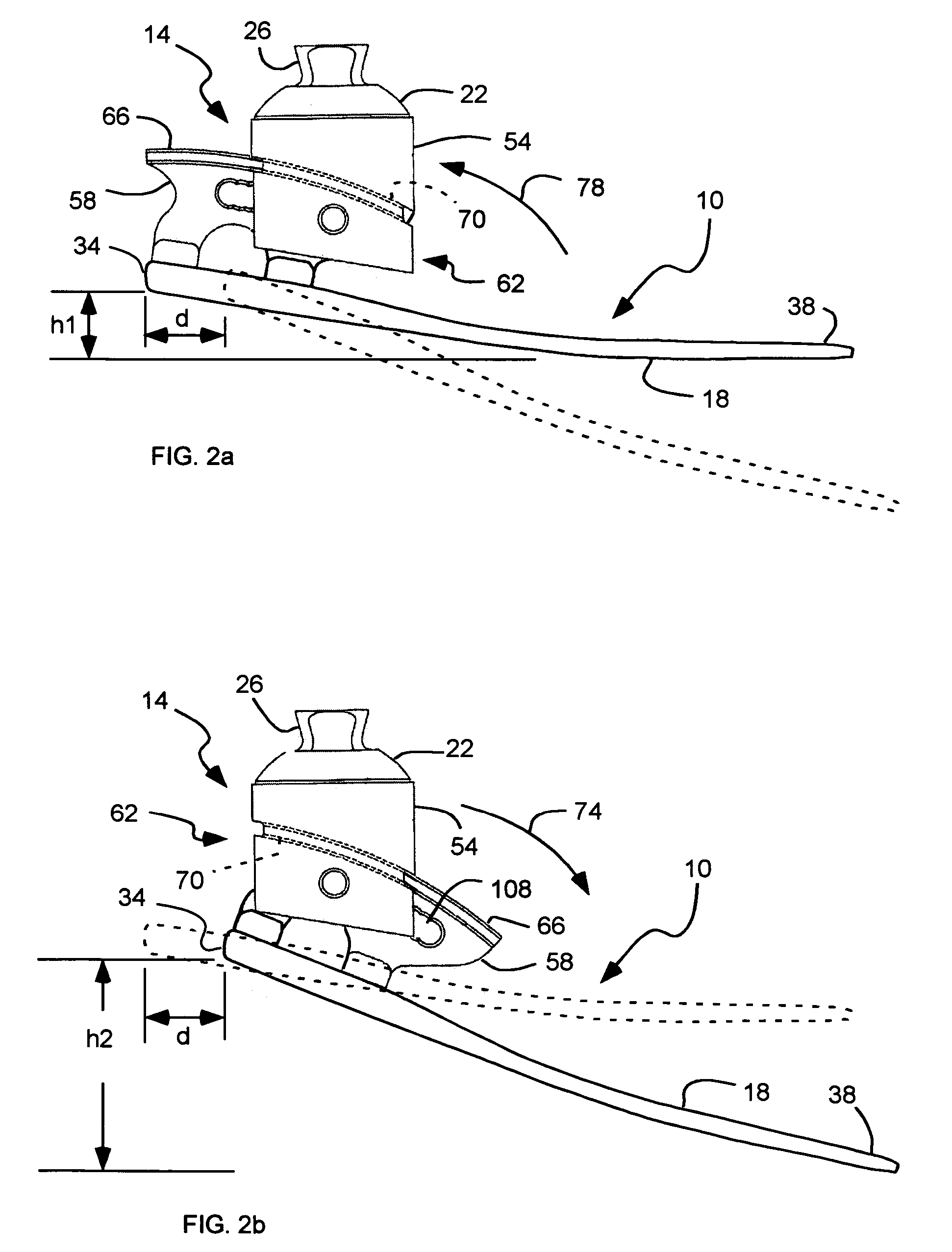
[0036]As illustrated in FIGS. 1-6, a prosthetic foot, indicated generally at 10, with an adjustable ankle, indicated generally at 14, in accordance with the present invention is shown for adjusting the prosthetic foot. The adjustable ankle 14 can adjust the angle of the foot 10, and the elevation of the heel. The adjustable ankle 14 can be utilized to quickly and easily adjust the foot 10 for use with different s...


PUM


Abstract

A prosthetic foot with an adjustable ankle includes an upper portion coupled to a socket of an amputee. A lower portion is adjustably coupled to the upper portion, and is attached to a foot member with heel and toe sections. A movable coupling is disposed between the upper and lower portions, and includes a displacement member slidably coupled to a displacement track. The movable coupling allows the toe section to pivot downward and the heel section to simultaneously displace forward. The adjustable ankle can be adjusted with an actuator coupled to a tractor bolt coupled between the upper and lower portions. A sensor is associated with the upper portion or the lower portion to sense frequency of contact, force of contact, or orientation of the upper portion or the lower portion, and to output a corresponding output signal.

Description

[0001]This is a continuation-in-part application of U.S. application Ser. No. 10 / 970,679, filed Oct. 20, 2004, now U.S. Pat. No. 7,462,201 which is a continuation-in-part of U.S. application Ser. No. 10 / 690,941, filed Oct. 21, 2003 now U.S. Pat. No. 6,966,933.BACKGROUND OF THE INVENTION[0002]1. Field of the Invention[0003]The present invention relates generally to a prosthetic foot with an adjustable ankle. More particularly, the present invention relates to a prosthetic foot that simultaneously pivots downward and displaces forward.[0004]2. Related Art[0005]Many individuals have lost a limb for various reasons including war, accident, or disease. In most instances these individuals are not only able to live relatively normal lives, but physically active lives as well. Oftentimes, these individuals are aided in their everyday lives by a prosthetic limb. The objective of prosthesis is to provide an artificial limb that simulates the function and natural feel of the replaced limb.[000...

Claims


Application Information

Patent Timeline
Patent Type & Authority Patents(United States)
IPC IPC(8): A61F2/64A61F2/48A61F2/00A61F2/50A61F2/66A61F2/70A61F2/76
CPCA61F2/6607A61F2/68A61F2002/30172A61F2002/30354A61F2002/30359A61F2002/30405A61F2002/30428A61F2002/30433A61F2002/30471A61F2002/30525A61F2002/5018A61F2002/502A61F2002/5021A61F2002/5039A61F2002/6621A61F2002/6642A61F2002/6664A61F2002/6685A61F2002/701A61F2002/704A61F2002/705A61F2002/707A61F2002/7615A61F2002/762A61F2002/7625A61F2002/7635A61F2002/765A61F2220/0025A61F2220/0033A61F2220/0041A61F2220/0091A61F2230/0052A61F2/70
Inventor CHRISTENSEN, ROLAND J.
Owner FREEDOM INNOVATIONS INC
Learn More