Adapter mechanism for explosive ordnance disrupter apparatus

Inactive Publication Date: 2009-05-19
THE UNITED STATES OF AMERICA AS REPRESENTED BY THE SECRETARY OF THE NAVY
View PDF21 Cites 13 Cited by
  • Summary
  • Abstract
  • Description
  • Claims
  • Application Information

AI Technical Summary

Benefits of technology

[0007]It is a primary object of the present invention to provide disrupter apparatus that allows one robot to accomplish both tasks of window breaking and bomb disruption.

Problems solved by technology

Since such robots are extremely expensive, the use of two different robots is not an option.

Method used


Image

  • Adapter mechanism for explosive ordnance disrupter apparatus
  • Adapter mechanism for explosive ordnance disrupter apparatus
  • Adapter mechanism for explosive ordnance disrupter apparatus

Examples


Embodiment Construction

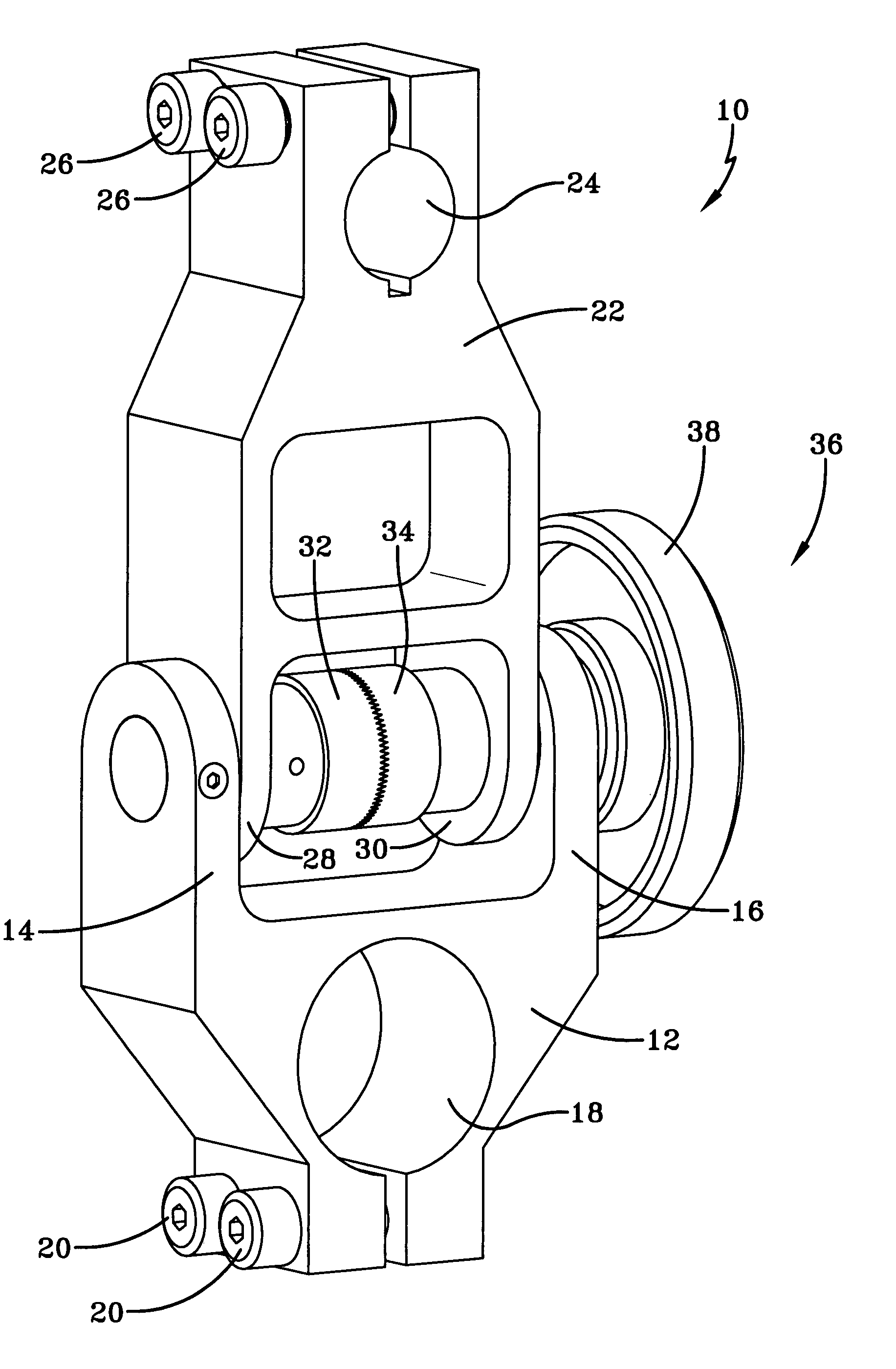
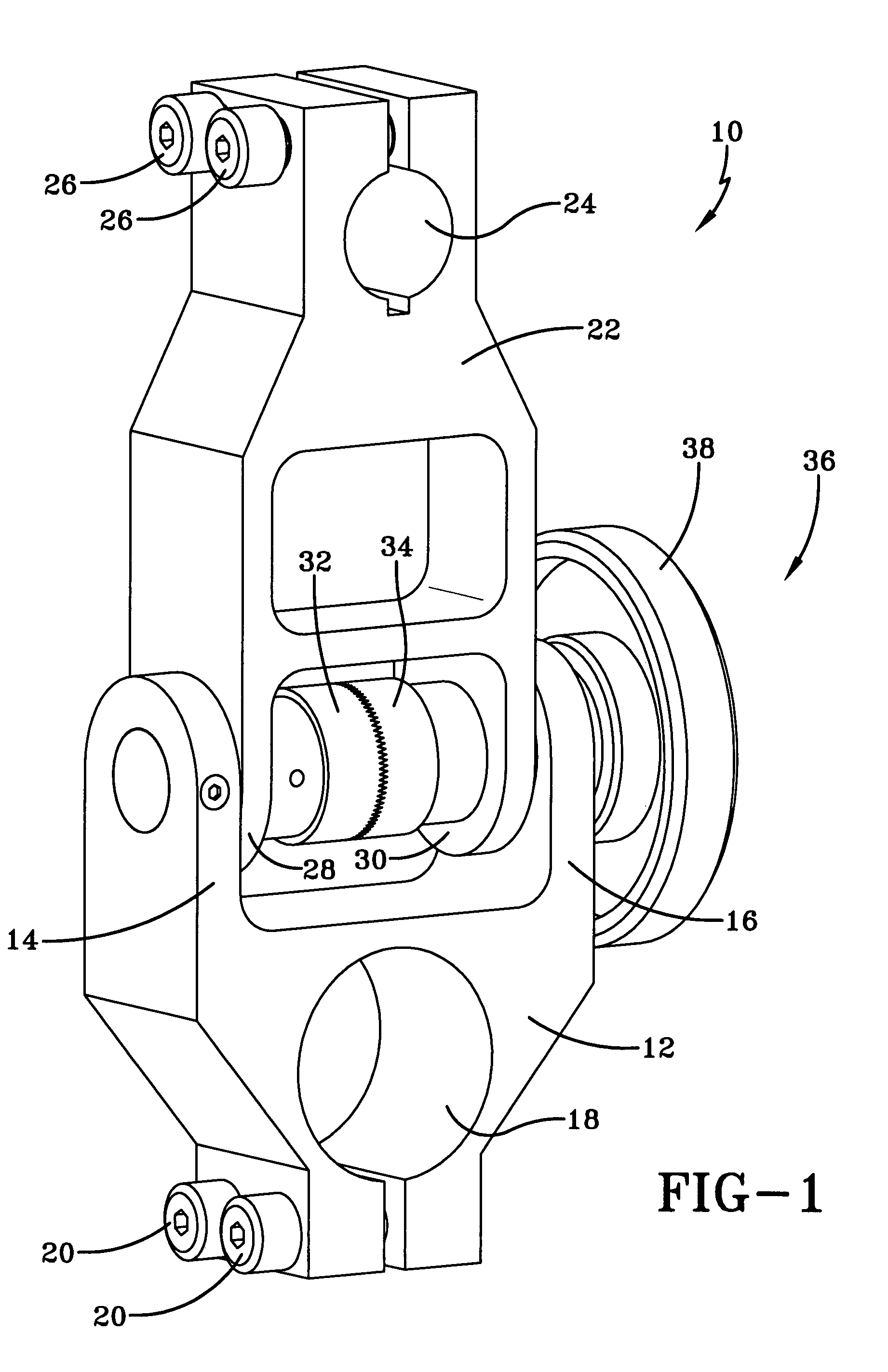
[0019]Referring now to FIG. 1 there is illustrated an exemplary embodiment of an adapter mechanism 10 in accordance with the present invention. The adapter 10 includes a generally “Y” shaped yoke 12 having first and second arms 14 and 16. Adapter 10 has an aperture 18 into which is placed the barrel of a primary disrupter with the barrel of the primary disrupter being held in position relative to the yoke by means of screws 20. A mount 22 is rotatable relative to the yoke 12. The mount 22 includes an aperture 24 into which is placed the barrel of a supplemental disrupter, with the barrel of the supplemental disrupter being held in position relative to the mount by means of screws 26.

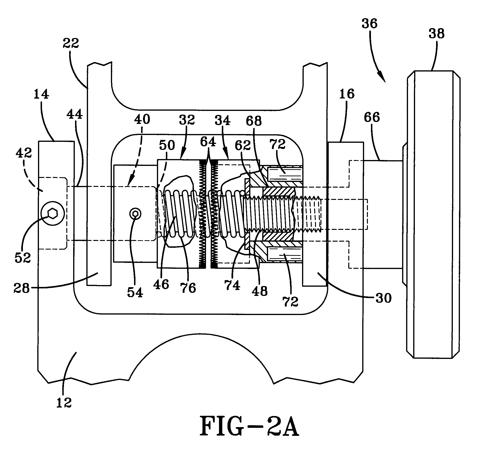
[0020]Extending between depending arms 28 and 30 of mount 22 are two couplers 32 and 34. These two couplers are disengageable with one another to adjust the angle of the mount 22 relative to that of the yoke 12. Thereafter, the two couplers 32 and 34 are engageable with one another to lock the mount 22 i...


PUM


Abstract

An adapter mechanism for use with an explosive ordnance disrupter arrangement. The adapter includes a yoke and a mount rotatable relative to the yoke to assume a desired angular orientation, which is locked in the desired position. The yoke may be mounted on an explosive ordnance primary disrupter. The mount carries a supplemental disrupter.

Description

STATEMENT OF GOVERNMENT INTEREST[0001]The invention described herein may be manufactured and used by or for the Government of the United States of America for Governmental purposes without the payment of any royalties thereon or therefor.BACKGROUND OF THE INVENTION[0002]1. Field of the Invention[0003]The invention in general relates to explosive ordnance disposal, and more particularly to a novel mechanism for use with a primary disrupter and a supplemental disrupter arrangement.[0004]2. Description of the Prior Art[0005]A disrupter is a primary tool used by explosive ordnance disposal technicians. The disrupter is basically a gun barrel positioned on a mount and is designed to fire various projectiles at a bomb with the intention of preventing it from exploding. Typically, the barrel is directed at a particular component of the bomb to disrupt that component. Various projectiles may be accommodated by the disrupter including lead and steel shot, hollow point slugs, bean bags, solid...

Claims


Application Information

Patent Timeline
IPC IPC(8): F42B33/00F16C11/06F41A19/05F41C23/00F41F1/10F41F5/00
CPCF16C11/10F42D5/04Y10T403/32861Y10T403/32868
Inventor STROHMAN, SCOTT A.
Owner THE UNITED STATES OF AMERICA AS REPRESENTED BY THE SECRETARY OF THE NAVY
Why Eureka
Try Eureka