Trail camera

a technology of trail cameras and cameras, applied in the field of trail cameras, can solve the problems of limiting the maneuverability of trail cameras, increasing the probability that trail cameras will be detected by vandals, and cameras may not be maneuvered or otherwise positioned

Inactive Publication Date: 2009-05-19
BUSHNELL
View PDF16 Cites 106 Cited by
  • Summary
  • Abstract
  • Description
  • Claims
  • Application Information

AI Technical Summary

Benefits of technology

[0007]The present invention solves the above-described problems and provides a distinct advance in the art of trail cameras. More particularly, the invention provides a trail camera having one or more hinges to enable pivoting of the trail camera after mounting to a fixed object. Such functionality enables the trail camera to be mounted at an elevated position while still enabling the camera to capture images near the ground.

Problems solved by technology

Unfortunately, due to theft and environmental conditions, trail cameras must be secured to a fixed object, such as a tree, through the use of screws, bolts, and other similar fixed securing devices.
While such securing devices may sometimes deter theft and withstand environmental conditions, they limit the maneuverability of the trail cameras such that the cameras may not be maneuvered or otherwise positioned after installation.
This limitation additionally requires trail cameras to be placed in close vertical proximity to the desired recording location.
Such positioning of trail cameras in proximity to game and the ground increases the probability that the trail cameras will be detected by vandals who may attempt to steal, destroy, or access the prominently displayed trail cameras.
Furthermore, the positioning of trail cameras in vertical proximity to the game increases the probability that game, or other recording subjects, will detect the presence of the cameras and undesirably alter their behavior.

Method used


Image

  • Trail camera
  • Trail camera
  • Trail camera

Examples


Embodiment Construction

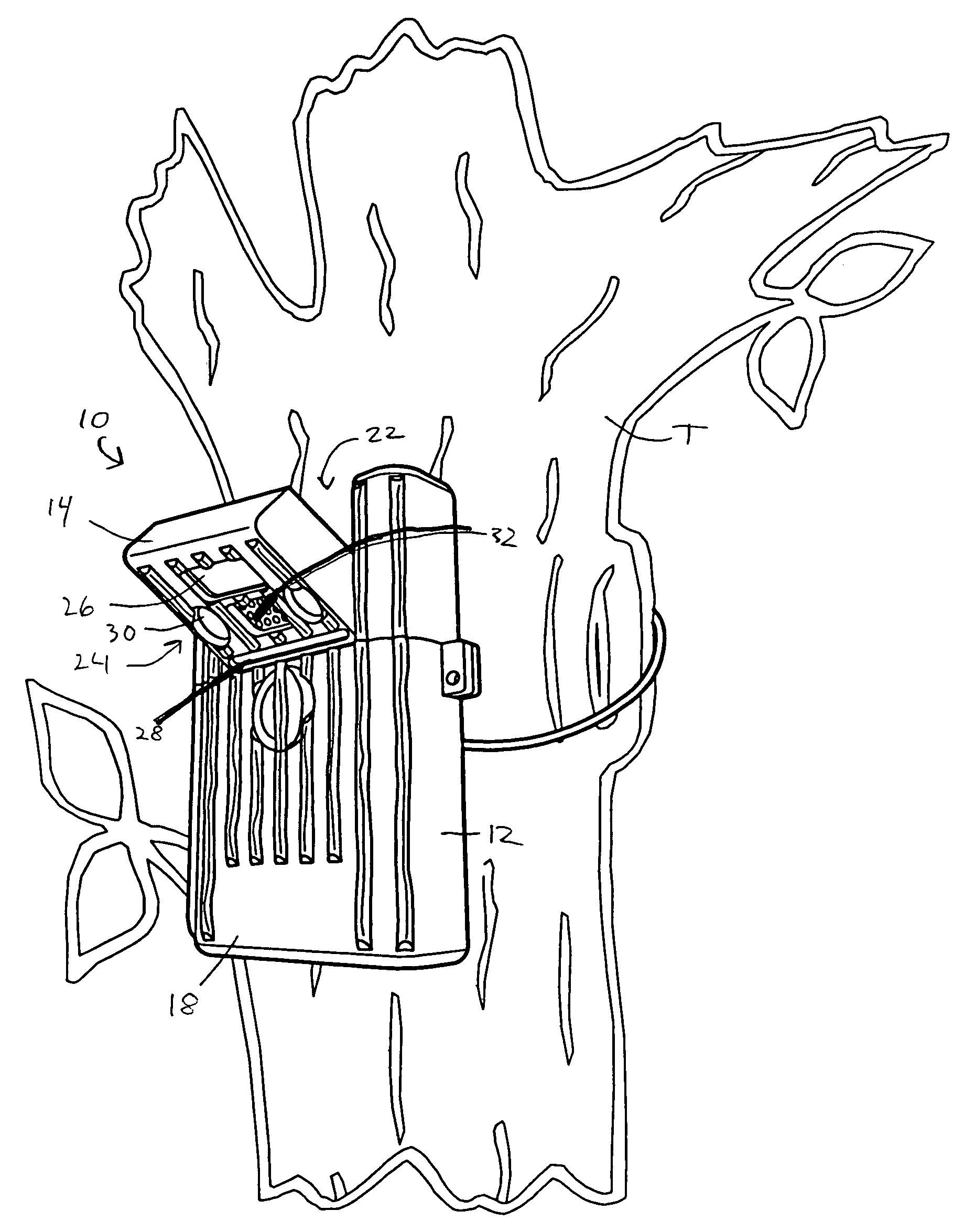
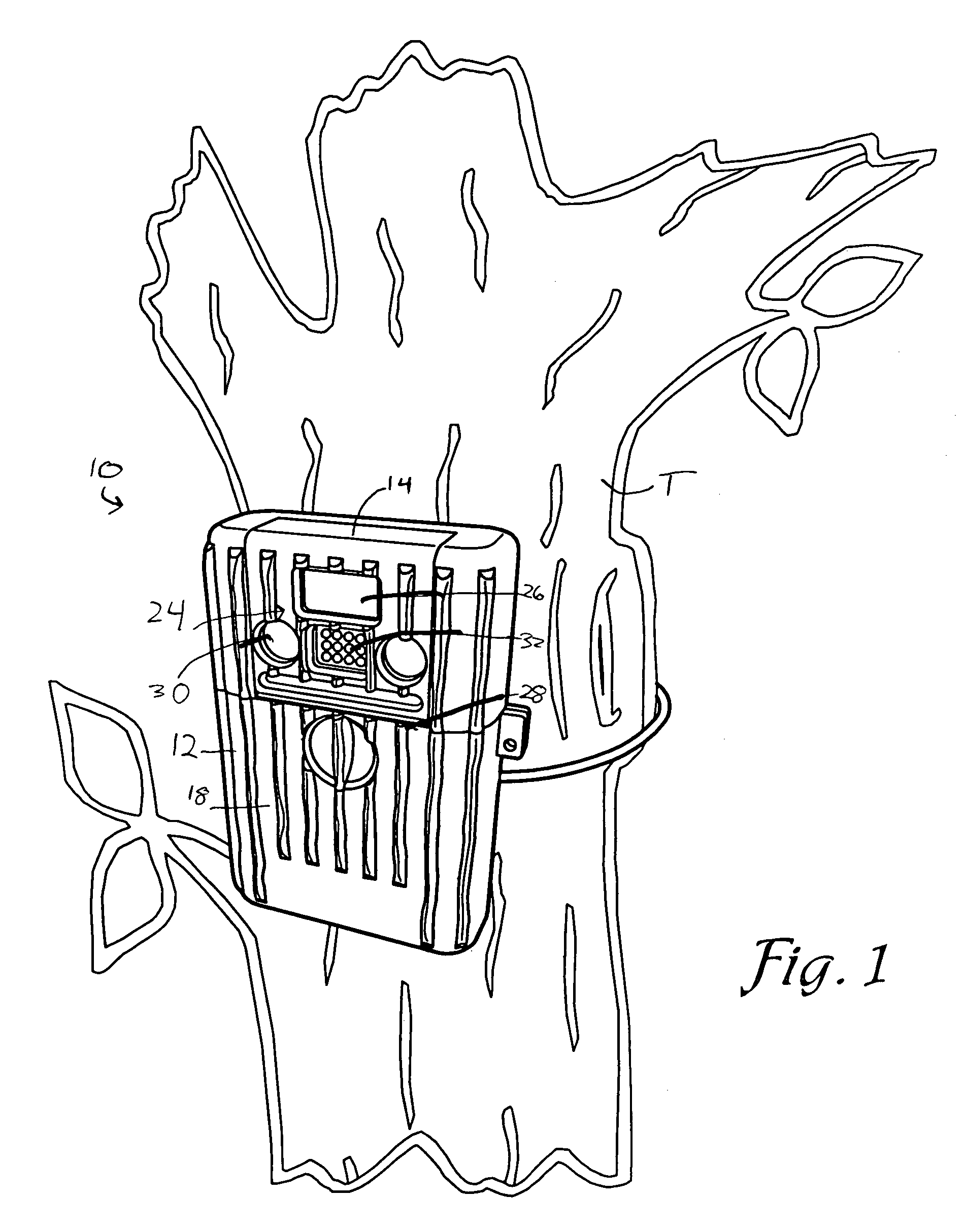
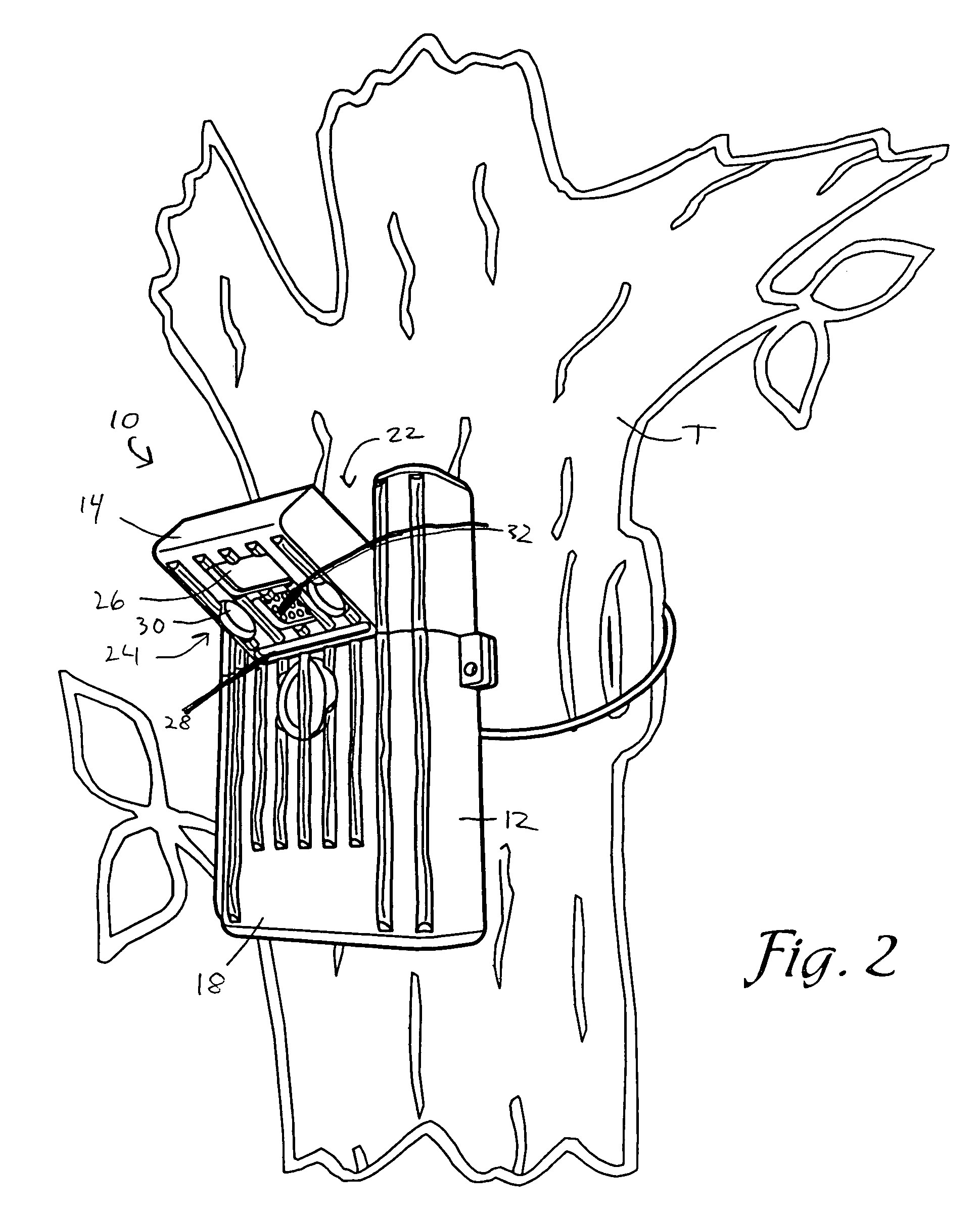
[0022]Reference will now be made in detail to various preferred embodiments of the present invention, examples of which are illustrated in the accompanying drawings. Wherever possible, the same reference numbers are used throughout the drawings to refer to the same or like parts.

[0023]Referring to FIGS. 1-6, a trail camera 10 is shown constructed in accordance with various preferred embodiments of the present invention. As is described below in more detail, the trail camera 10 is operable to be mounted to a fixed object, such as a tree T, pole, wall, a natural or man-made formation, etc, to automatically or selectively record an image. Preferably, the trail camera 10 is operable to mount to an elevated position on the tree T.

[0024]The trail camera 10 broadly includes a housing 12, a camera section 14 coupled with the housing 12, and a first hinge 16 coupled with the housing 12 and operable to pivot at least a portion of the trail camera 10 after the housing 12 is secured to the tree...


PUM


Abstract

A trail camera having one or more hinges to provide pivoting of the trail camera after mounting to a fixed object is disclosed. The hinges allow pivoting of a housing and / or a camera section after the trail camera is mounted to enable a user to direct the trail camera towards a target location to capture an image regardless of the particular mounting orientation of the camera. Such a configuration enables the trail camera to be mounted at a vertical elevation above the target location while still recording events in proximity to the target location.

Description

BACKGROUND OF THE INVENTION[0001]1. Field of the Invention[0002]The present invention relates to trail cameras. More particularly, the invention relates to a trail camera for mounting to a fixed object and having one or more hinges to enable pivoting of the trail camera relative to the object.[0003]2. Description of the Related Art[0004]Trail cameras are often used to automatically capture images at a remote location by utilizing a sensor to trigger a camera device. For example, trail cameras are commonly utilized by hunters to record game activity, such as the passing of a deer, at a remote hunting location. After installation, a hunter periodically access the trail camera to determine the existence and nature of any game activity.[0005]Unfortunately, due to theft and environmental conditions, trail cameras must be secured to a fixed object, such as a tree, through the use of screws, bolts, and other similar fixed securing devices. While such securing devices may sometimes deter th...

Claims


Application Information

Patent Timeline
Patent Type & Authority Patents(United States)
IPC IPC(8): G03B17/00
CPCF16M11/10F16M13/02G03B17/00Y10T70/30
Inventor CROSS, BILLSTEPHENS, DARIN
Owner BUSHNELL
Why Eureka
Try Eureka