Multilevel structured surfaces

a structure and surface technology, applied in the field of multi-level structured surfaces, can solve the problems of droplet not returning to its position on the top of the structure, existing surfaces not providing the desired reversible control of wetting,

Active Publication Date: 2009-05-19
ALCATEL-LUCENT USA INC
View PDF1 Cites 41 Cited by
  • Summary
  • Abstract
  • Description
  • Claims
  • Application Information

AI Technical Summary

Problems solved by technology

Unfortunately existing surfaces do not provide the desired reversible control of wetting.
Unfortunately, the droplet may not return to its position on top of the structure and with a high contact angle when the voltage is then turned off.

Method used


Image

  • Multilevel structured surfaces
  • Multilevel structured surfaces
  • Multilevel structured surfaces

Examples


Embodiment Construction

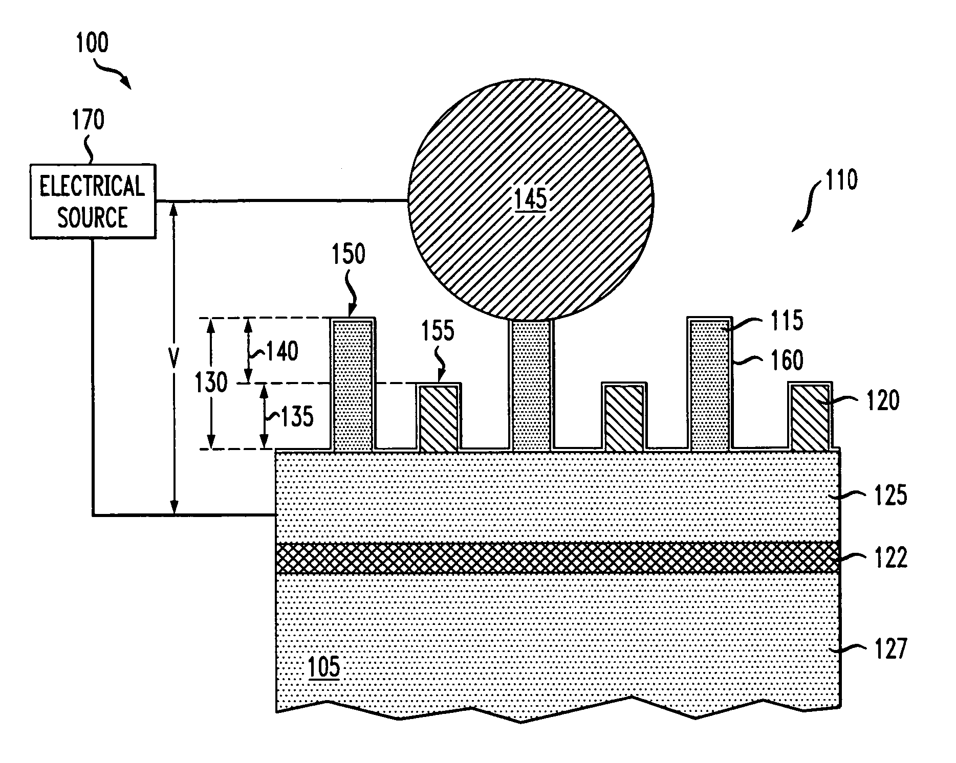
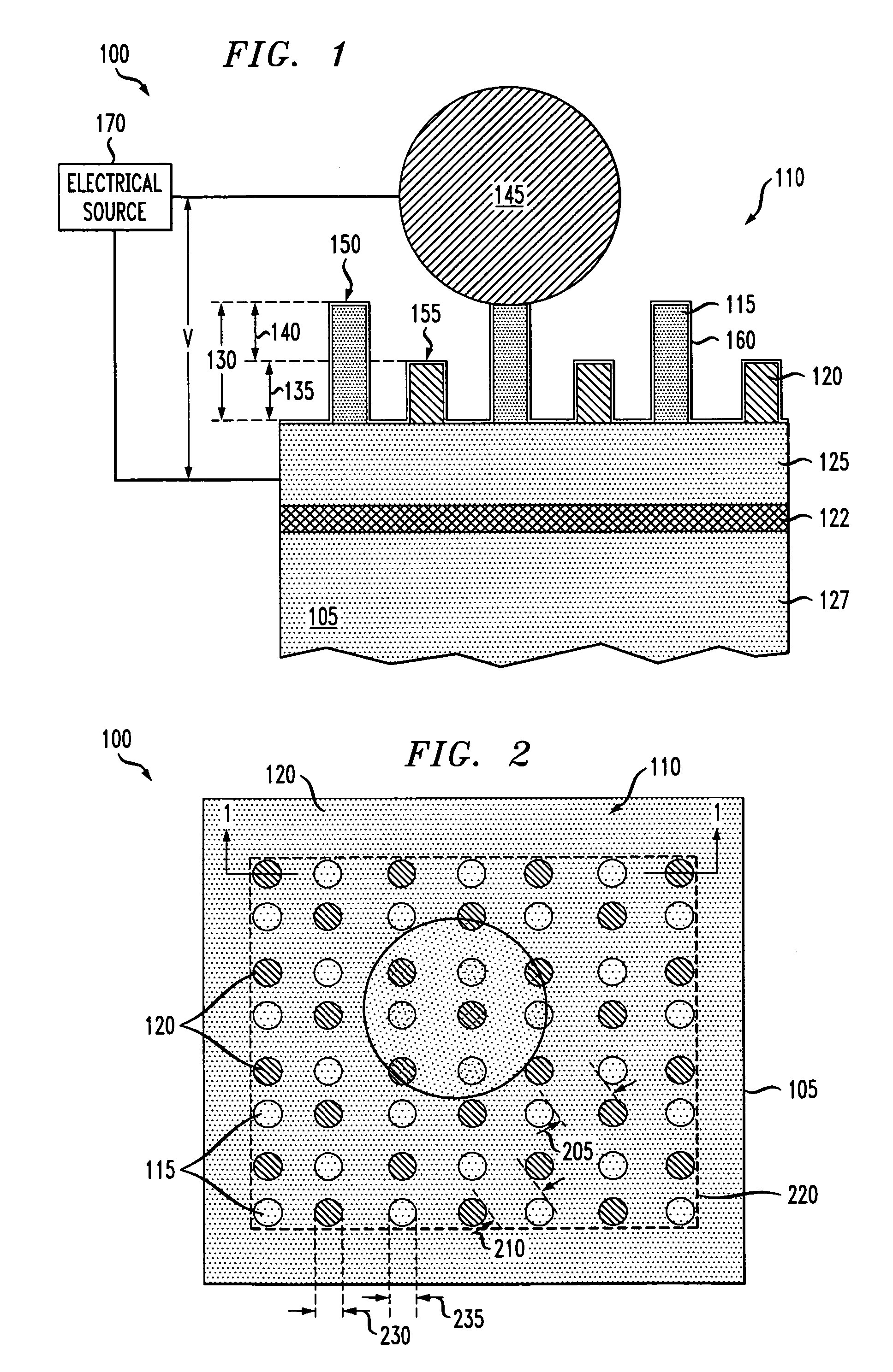
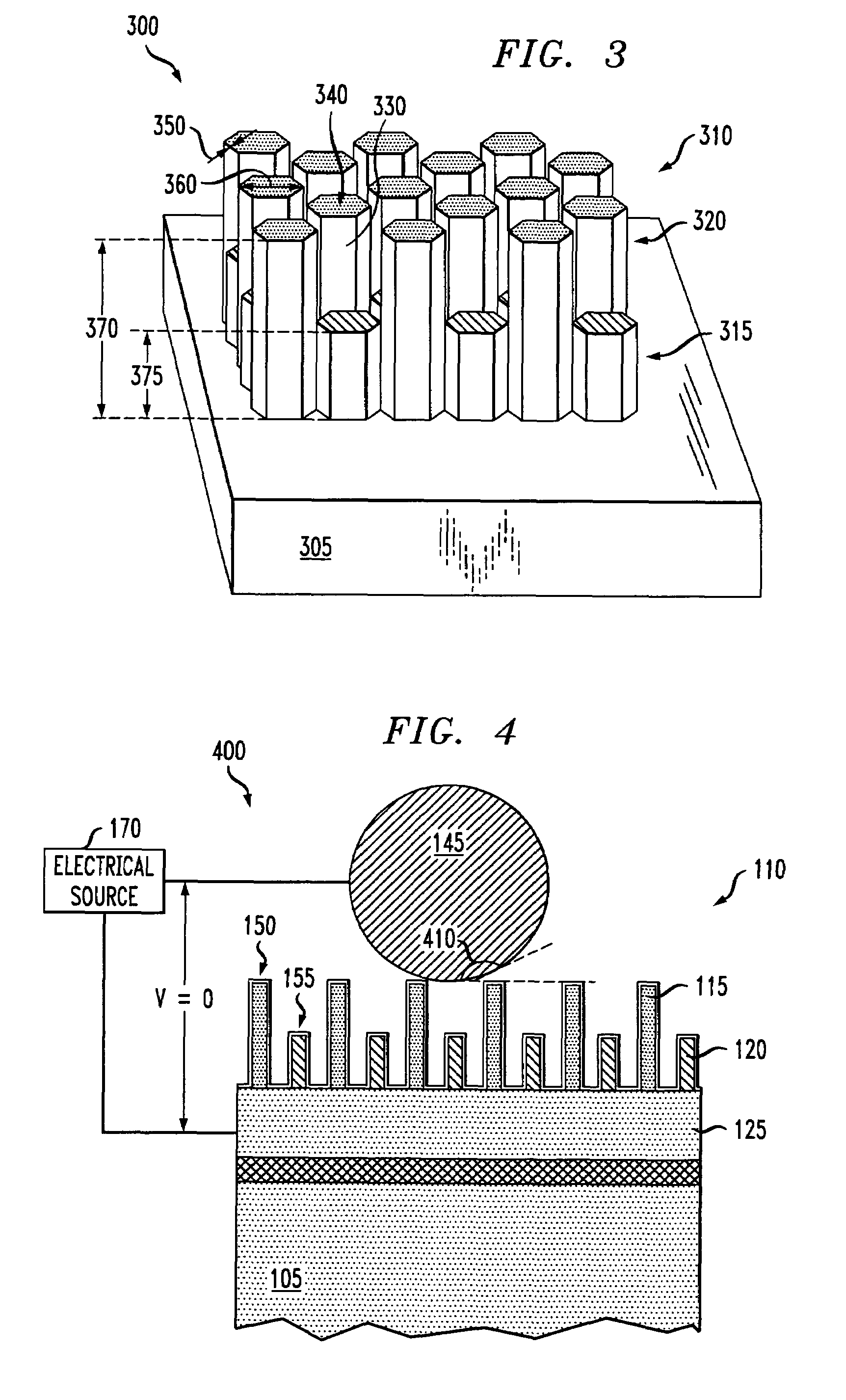
[0013]As part of the present invention it is recognized that de-wetting a surface by returning a fluid to the tops of fluid-support-structures can be impeded when the fluid contacts a base layer that the fluid-support-structures are located on. While not limiting the scope of the invention by theory, it is thought that there are energy losses associated with moving the contact line (e.g., the intersection between the fluid, air and base layer) as the fluid spreads over a surface during wetting. These energy losses necessitate the introduction of additional energy to de-wet the surface. Examples of introducing energy to de-wet a surface by heating the surface are presented U.S. patent application Ser. Nos. 11 / 227,759 and 11 / 227,808, which are incorporated by reference herein in their entirety.

[0014]In contrast, embodiments of the present invention provide an apparatus having a surface with multilevel fluid-support-structures. The multilevel fluid-support-structures facilitate de-wett...


PUM


Abstract

An apparatus comprising a substrate having a surface with electrically connected and electrically isolated fluid-support-structures thereon. Each of the fluid-support-structures have at least one dimension of about 1 millimeter or less. The electrically connected fluid-support-structures are taller than the electrically isolated fluid-support-structures.

Description

TECHNICAL FIELD OF THE INVENTION[0001]The present invention is directed, in general, to reversibly controlling the wetability of a surface.BACKGROUND OF THE INVENTION[0002]It is desirable to reversibly wet or de-wet a surface, because this allows one to reversibly control the mobility of a fluid on a surface. Controlling the mobility of a fluid on a surface is advantageous in microfluidics applications where it is desirable to repeatedly move a fluid to a designated location, immobilize the fluid and remobilize it again. It is also advantageous to control the mobility of a fluid on a surface of a body when moving the body through a fluid. Unfortunately existing surfaces do not provide the desired reversible control of wetting.[0003]For instance, certain surfaces with raised features, such as posts or pins, may provide a superhydrophobic surface. That is, a droplet of liquid on a superhydrophobic surface will appear as a suspended drop having a contact angle of at least about 140 deg...

Claims


Application Information

Patent Timeline
Patent Type & Authority Patents(United States)
IPC IPC(8): H02H3/00
CPCB01L3/502746B01L3/502792B01L2300/0809B01L2300/089B01L2300/166B01L2400/0427B01L2400/082
Inventor KRUPENKIN, THOMAS NIKITATAYLOR, JOSEPH ASHLEY
Owner ALCATEL-LUCENT USA INC
Why Eureka
Try Eureka