System and method for gas shut off in a subterranean well

a technology for subterranean wells and wells, applied in the direction of valve operating means/release devices, wellbore/well accessories, sealing/packing, etc., can solve the problems of high cost and relatively complex devices

Inactive Publication Date: 2009-05-26
SCHLUMBERGER TECH CORP
View PDF13 Cites 82 Cited by
  • Summary
  • Abstract
  • Description
  • Claims
  • Application Information

AI Technical Summary

Problems solved by technology

However, gas inflow into the hydrocarbon liquid being produced can lead to detrimental results.
The problem can exist in one or more producing reservoirs within the same well.
Those attempts, however, have relied on relatively complex, high cost devices that are either controlled from the surface or moved downhole via intervention techniques.

Method used


Image

  • System and method for gas shut off in a subterranean well
  • System and method for gas shut off in a subterranean well
  • System and method for gas shut off in a subterranean well

Examples


Embodiment Construction

[0009]In the following description, numerous details are set forth to provide an understanding of the present invention. However, it will be understood by those of ordinary skill in the art that the present invention may be practiced without these details and that numerous variations or modifications from the described embodiments may be possible.

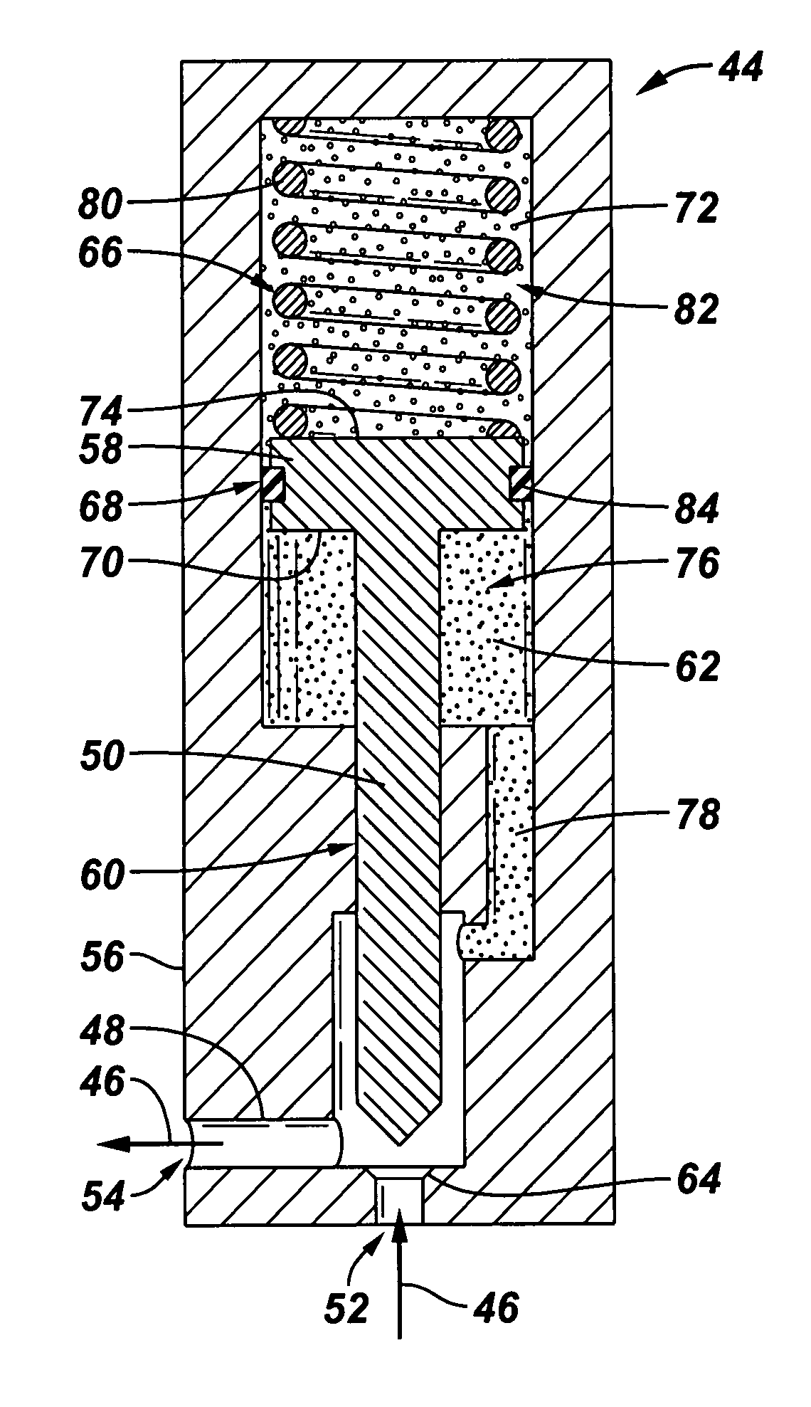
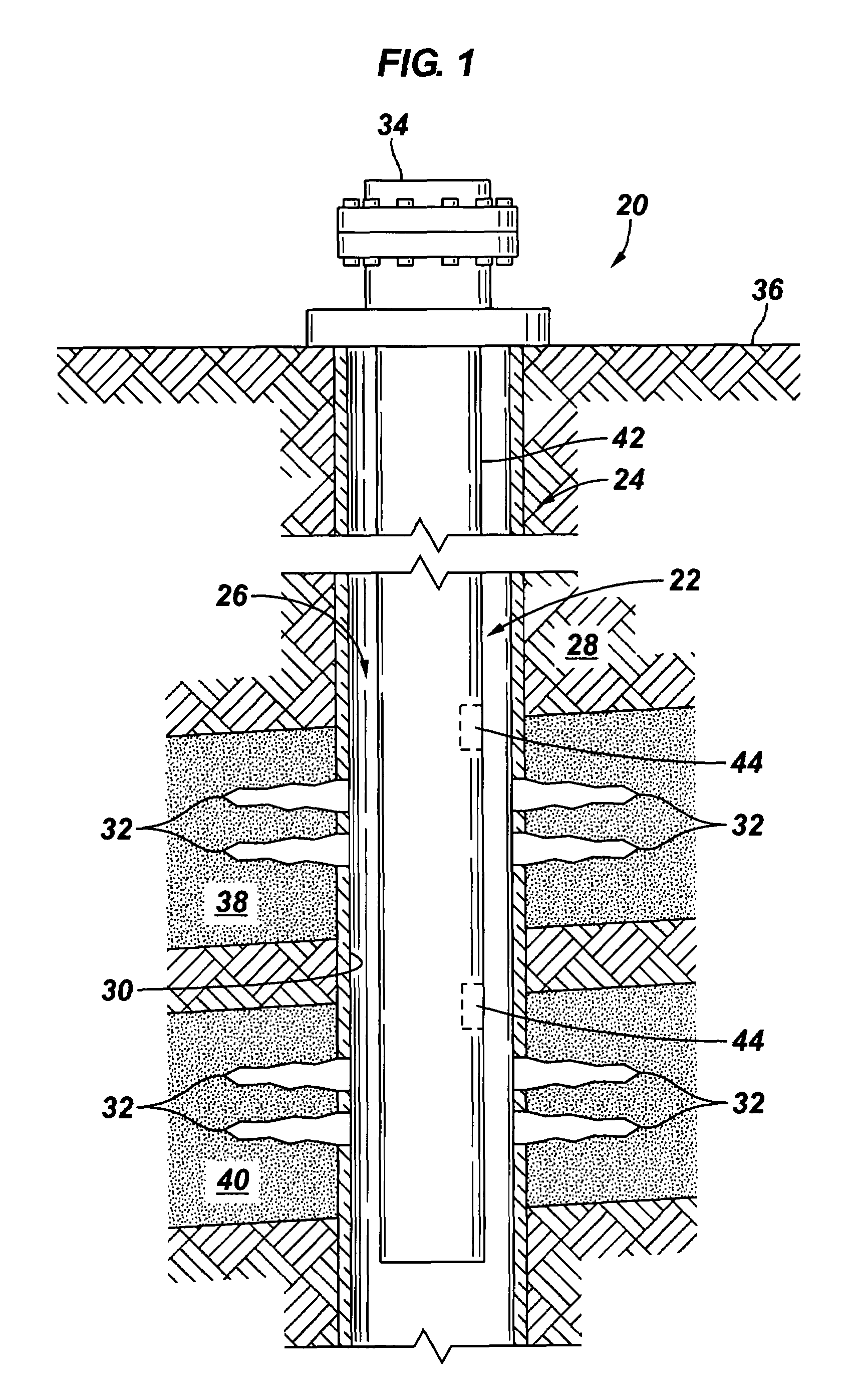
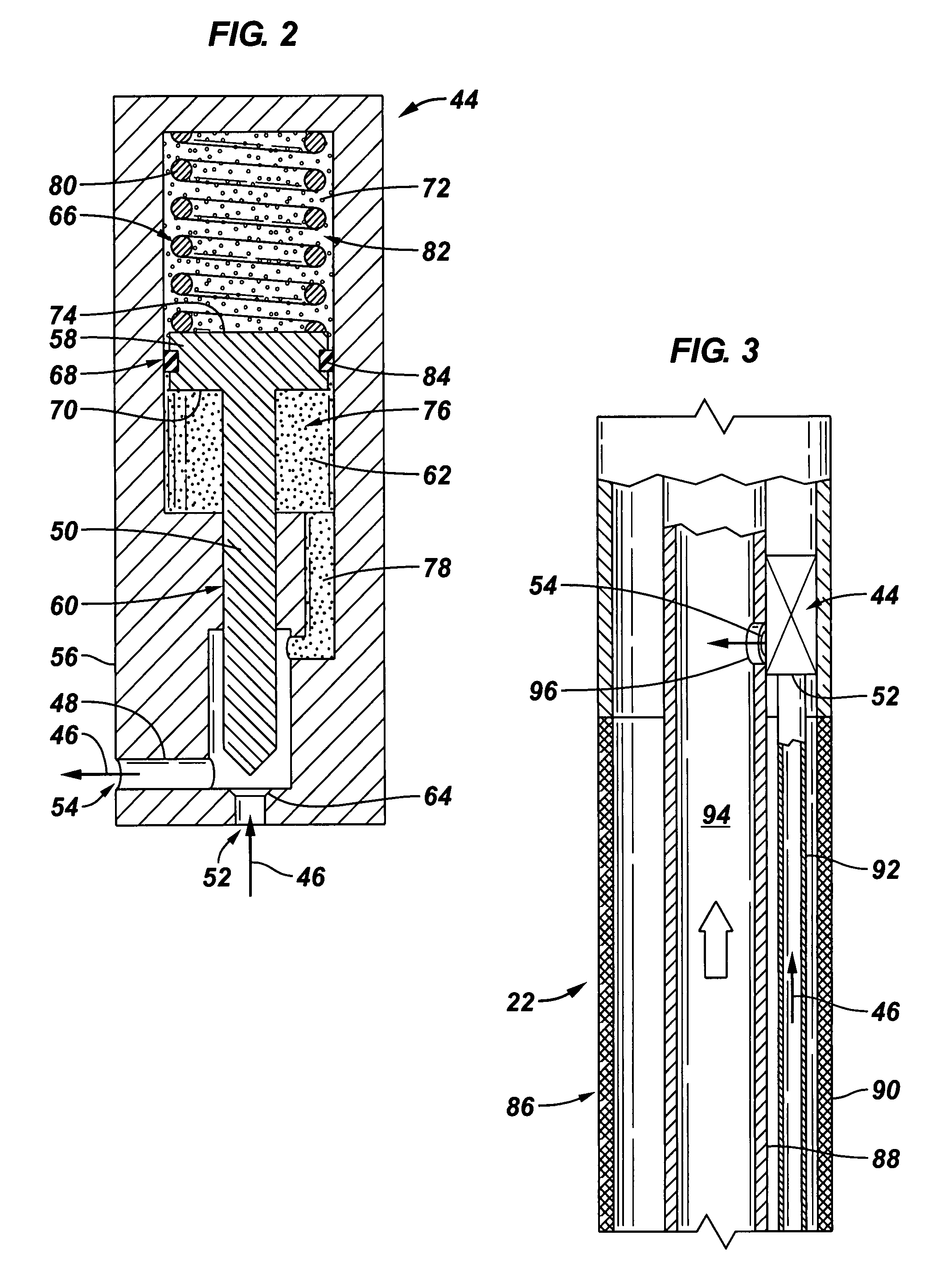
[0010]The present invention relates to a system and methodology for controlling gas saturation of a liquid produced from a well. One or more valves are combined with one or more downhole tools to control the influx of gas into the downhole tools during production of a desired liquid. Each valve may comprise a valve actuator system which is automatically actuated by allowing a lower viscosity fluid, namely gas, to migrate from a zone of higher pressure in the valve to a zone of lower pressure in the valve. Once the gas flows into the zone of lower pressure, the fluid forces acting on the valve are equalized, enabling a spring device to trans...


PUM


Abstract

A gas inflow control system is used in a well. A downhole tool is combined with an automatic valve that is automatically actuatable to a flow position in the presence of a well liquid flowing into the downhole tool. In the presence of gas flow into the valve, the valve automatically transitions toward or to a closed position.

Description

CROSS-REFERENCE TO RELATED APPLICATIONS[0001]The following is based upon and claims priority to U.S. Provisional Application Ser. No. 60 / 593,207 filed Dec. 21, 2004.BACKGROUND[0002]The invention generally relates to a system and method for producing well fluids from a wellbore. Many production wells are used to produce a desired liquid, such as a hydrocarbon based liquid, from subterranean formations. However, gas inflow into the hydrocarbon liquid being produced can lead to detrimental results. For example, the level of gas saturation can increase over time to a point where the gas cut is too high to economically produce the liquid hydrocarbon. The problem can exist in one or more producing reservoirs within the same well.[0003]Attempts have been made to control the gas saturation of produced liquid. Those attempts, however, have relied on relatively complex, high cost devices that are either controlled from the surface or moved downhole via intervention techniques.SUMMARY[0004]The...

Claims


Application Information

Patent Timeline
Patent Type & Authority Patents(United States)
IPC IPC(8): E21B34/06
CPCE21B34/08E21B43/12E21B43/38F16K31/1221
Inventor MACDOUGALL, THOMAS D
Owner SCHLUMBERGER TECH CORP
Why Eureka
Try Eureka