Dimmable rearview assembly having a glare sensor

a rearview assembly and glare sensor technology, applied in the direction of optical radiation measurement, photometry using electric radiation detectors, instruments, etc., can solve the problems of compromising the electrical design, adding the cost of additional parts and assembly processes, and undetectable low optical gain

Inactive Publication Date: 2009-06-09
GENTEX CORP
View PDF69 Cites 186 Cited by
  • Summary
  • Abstract
  • Description
  • Claims
  • Application Information

AI Technical Summary

Problems solved by technology

Placement of the sensor close to the aperture often leads to the added cost of additional parts and assembly processes, and longer electrical connecting paths to the sensor often compromises the electrical design.
In the second sensor configuration in FIG. 4b, the sensor is placed at an appreciable distance from the aperture and has undesirably low optical gain.
The placement of the sensor may be convenient and less costly but for the overall design the reduction in optical gain, which may be severe, may compromise or even prevent satisfactory performance.
The disadvantage is that instead of concentrating the light and adding optical gain as was accomplished in the first example, the light level is effectively attenuated because rays that would have come unobstructed through the aperture and struck the sensor before placing the diffuser in it are now spread out by the disbursing effect of the diffuser so that the proportion of the rays which reaches the sensor is diminished.
In addition, in the same model vehicle, the seats may have either light or dark upholstery, which may affect the light levels sensed by the glare sensor when the seats are within the field of view of the sensor.

Method used


Image

  • Dimmable rearview assembly having a glare sensor
  • Dimmable rearview assembly having a glare sensor
  • Dimmable rearview assembly having a glare sensor

Examples


Embodiment Construction

[0089]Reference will now be made in detail to the present preferred embodiment of the invention, an example of which is illustrated in the accompanying drawings. Wherever possible, the same reference numerals will be used throughout the drawings to refer to the same or like parts.

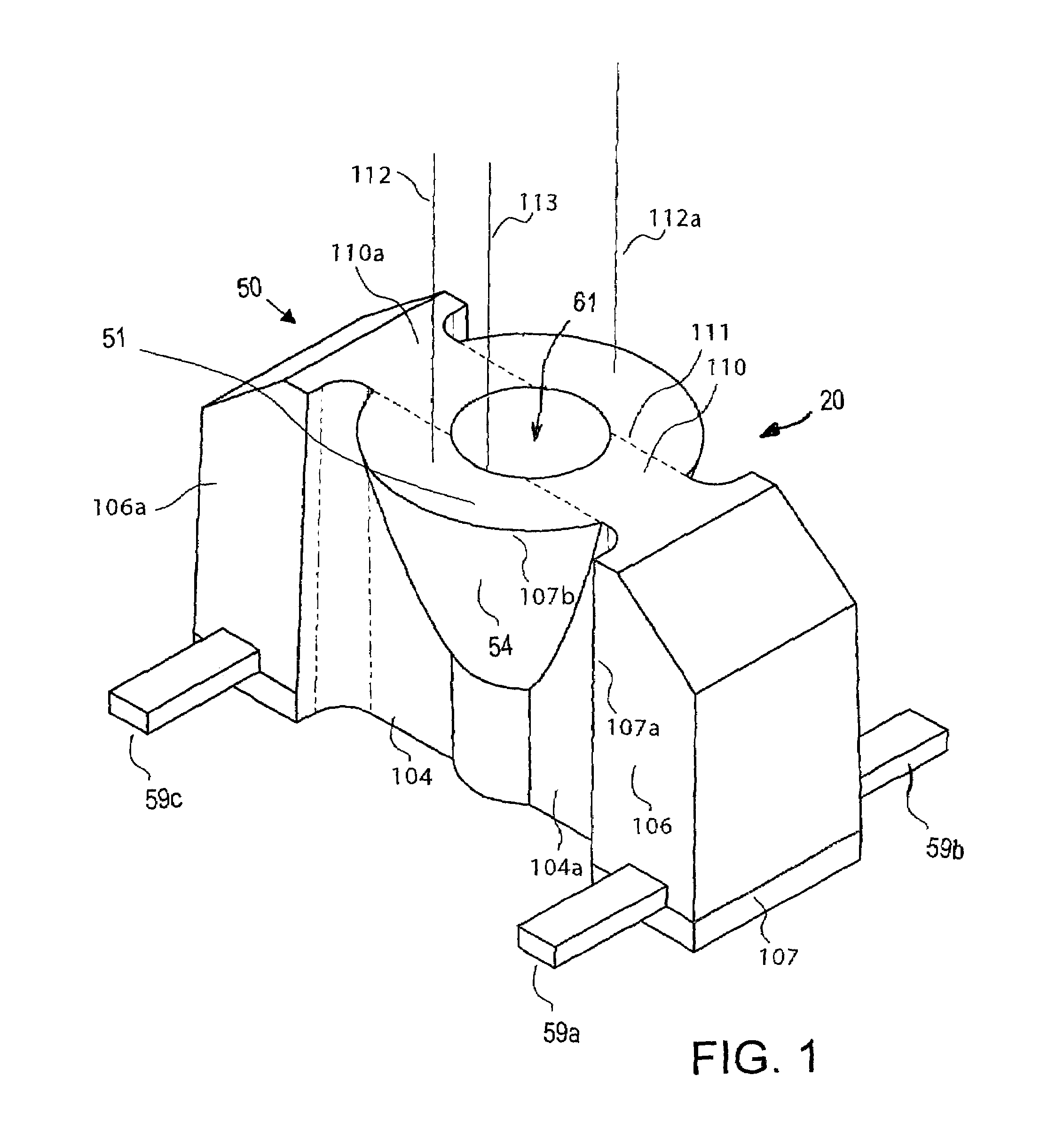
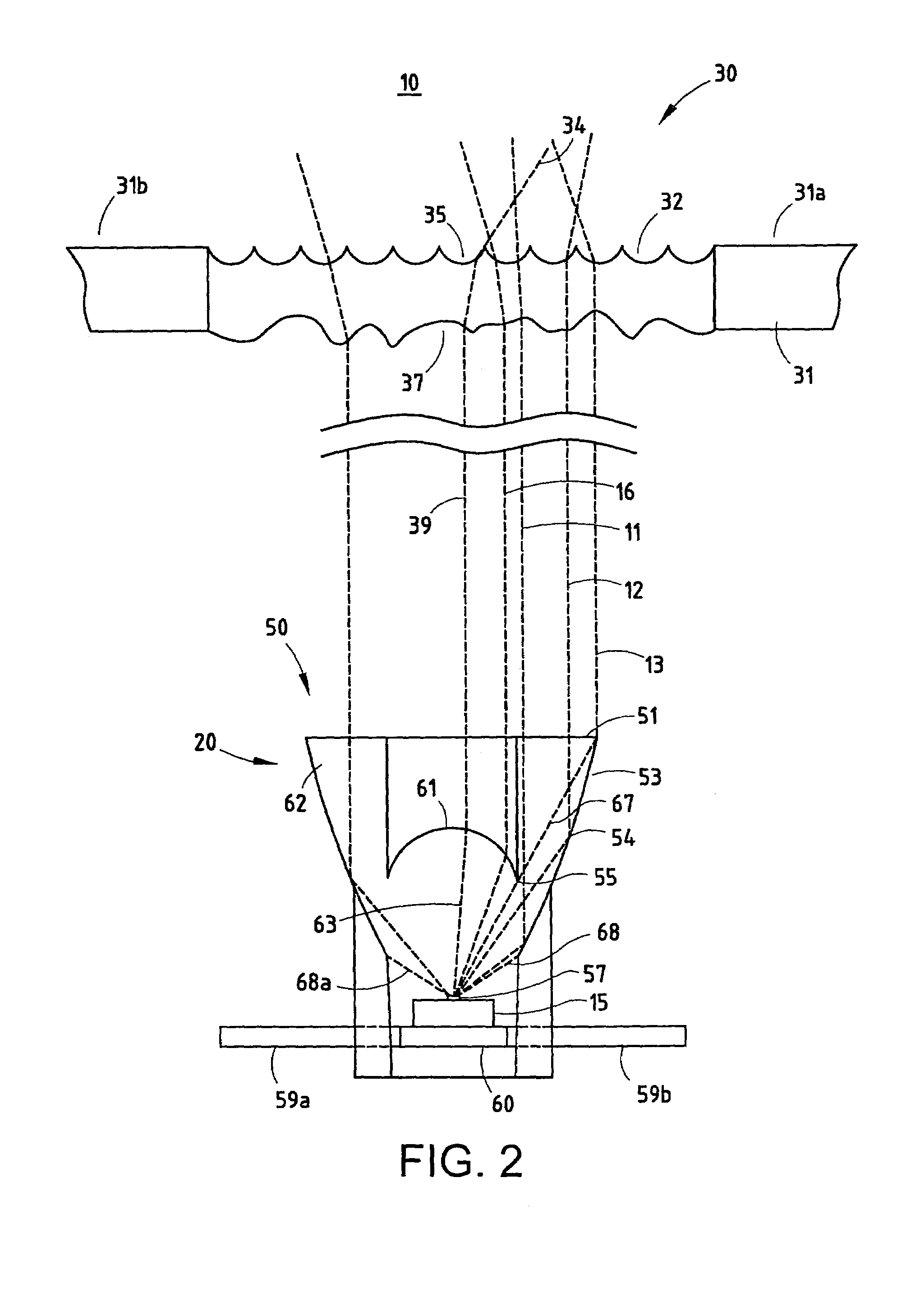
[0090]A sensor device 50 that is constructed in accordance with one embodiment of the present invention is shown in FIG. 1. A sensor subassembly 10 incorporating sensor device 50 is shown in FIG. 2. The sensor device 50 includes a support structure, such as a printed circuit board or a lead frame 60; an integrated sensing circuit 15 having an active sensing area 57 mounted on the support substrate for sensing optical radiation, preferably visible light; and an encapsulant 62 encapsulating the sensing circuit on the support structure. In general, the encapsulant 62 defines a lens structure 20 including an integral refracting lens portion 61 preferably having an elliptical refracting surface for focusing inci...


PUM


Abstract

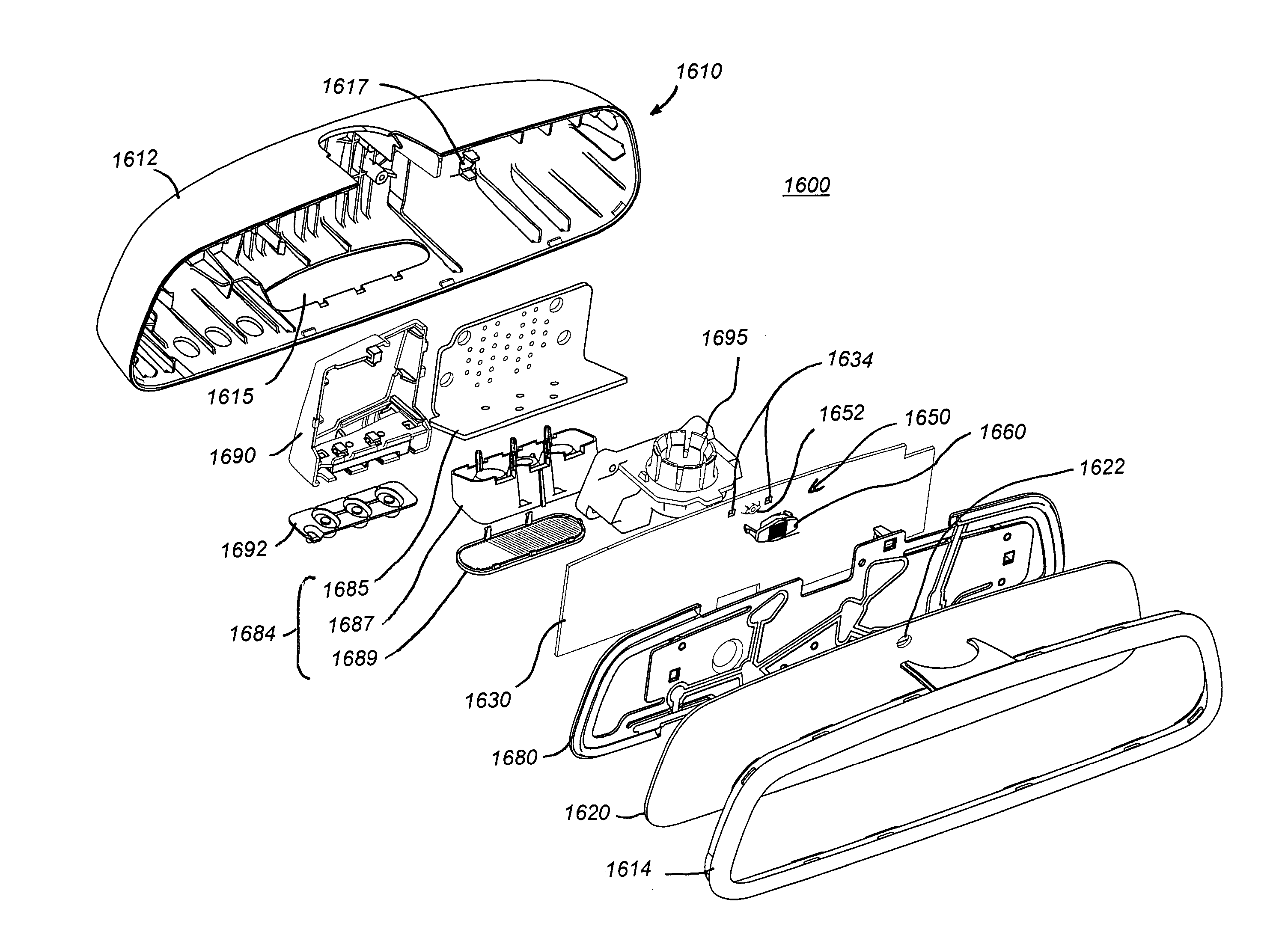
A rearview assembly of the present invention may include a housing adapted to be mounted to the vehicle, a rearview element disposed in the housing for providing an image to the driver of the rearward view from the vehicle, and a glare sensor positioned to receive light from passing through the rearview element. The glare sensor may be a surface-mounted to a circuit board. An optional secondary optical element may be disposed between the rearview element and the glare sensor. The optional secondary optical element may have an anamorphic lens for providing different fields of view horizontally versus vertically.

Description

CROSS-REFERENCE TO RELATED APPLICATIONS[0001]This application is a continuation-in-part of U.S. patent application Ser. No. 10 / 068,540 filed on Feb. 6, 2002, now U.S. Pat. No. 6,831,268 which is a continuation-in-part of U.S. patent application Ser. No. 10 / 043,977 filed on Jan. 10, 2002, now U.S. Pat. No. 6,679,608. The entire disclosure of each of the above applications is incorporated herein by reference.BACKGROUND OF THE INVENTION[0002]The present invention generally relates to an optical radiation sensor device, and more particularly to a sensor device incorporating a photosensor.[0003]Light sensors are used in a large number of different applications. In such light sensing applications, several characteristics of the sensing mechanism need to be in acceptable ranges and some further need to be characterized for specific light sensing applications. Other characteristics of the sensor may increase the range of applications for which the sensor is suitable and / or may provide for e...

Claims


Application Information

Patent Timeline
Patent Type & Authority Patents(United States)
IPC IPC(8): G02B5/08B60R1/08G01J1/42G01J1/46G02B5/02G02B17/08
CPCB60R1/088G01J1/42G01J1/46G02B5/0215G02B5/0221G02B5/0278G02B5/08G02B19/0028G02B19/0076G01J1/0271G01J1/0407G01J1/0411G01J1/0422G01J1/0474H01L2224/48091H01L2224/48247H01L2924/00014
Inventor OCKERSE, HAROLD C.BECHTEL, JON H.STAM, JOSEPH S.TUTTLE, DARIN D.RUMSEY, WAYNE J.WALSER, JEREMY A.
Owner GENTEX CORP
Why Eureka
Try Eureka