Transceiver

a transceiver and receiver technology, applied in the field of transceivers, can solve the problems of increasing the cost and complexity of the transponder, the antenna cannot efficiently broadcast the transmitted signal, and the requirement of low q antennas of low efficiency

Inactive Publication Date: 2009-06-09
SATO HLDG CORP
View PDF19 Cites 21 Cited by
  • Summary
  • Abstract
  • Description
  • Claims
  • Application Information

AI Technical Summary

Benefits of technology

[0019]In a preferred form the transceiver allows the transmission rate of data to be decoupled from both the Q factor of the antenna and the capacity of the DC storage means.
[0035]modulator means disposed between the antenna and the signal processor means for providing a fourth signal to the antenna for forming the second signal, the modulator means varying the voltage across the antenna in a substantially stepwise manner to affect a variation in the current flowing through the antenna between a low and a high value for allowing transmission of the second signal without substantially affecting the receiving efficiency of the antenna.
[0065]Preferably, the antenna is a coil tuned by a capacitor. As will be appreciated by those skilled in the art from the teaching herein, to transmit a signal from this type of single antenna transceiver (also known as a transponder) the current flowing in the coil is modulated or varied in some predetermined manner. Most preferably, this is achieved by the use of a small variable resistance in series between the antenna and the tuning capacitor to cause a variation in the current generated by the coil. In some preferred embodiments the small series resistance is modulated with an RF carrier and data is modulated onto the carrier for transmission by the antenna. Varying or modulating the value of this small resistance causes rapid changes in the current flowing in the coil that are not limited by the antenna tuning. Accordingly, the invention, in these embodiments, allows simultaneous reception at the first predetermined frequency and transmission at a second predetermined frequency different from the first.
[0067]The preferred embodiments of the invention overcome the prior art limitation of the transmission frequency having to be similar to the receive frequency, as they allow the transmission frequency to be completely decoupled from the tuned receiving frequency of the antenna. This, in turn, enables the transmission of higher or lower frequency signals from transponders with antennas tuned either lower or higher respectively than the transmission frequency.

Problems solved by technology

The need for separate antennae adds to the cost and complexity of the transponder.
Generally, these antennae are tuned to the received or interrogating frequency and, as such, the transmitted frequency can not differ greatly from the received frequency otherwise the antennae will not broadcast the transmitted signal efficiently.
To transmit data at a high speed a low efficiency low Q antenna is required, however, to receive signals with high efficiency a high Q antenna is required.
This contradiction precludes the use of a high efficiency antenna for high speed data transmission.
The transmission efficiency of all these systems is degraded by this tuning arrangement and otherwise compromised by the stray capacitance of the antenna coil.
Additionally, in passive transponders the electrical inertia of the power storage system limits the data rate.

Method used


Image

  • Transceiver
  • Transceiver
  • Transceiver

Examples


Embodiment Construction

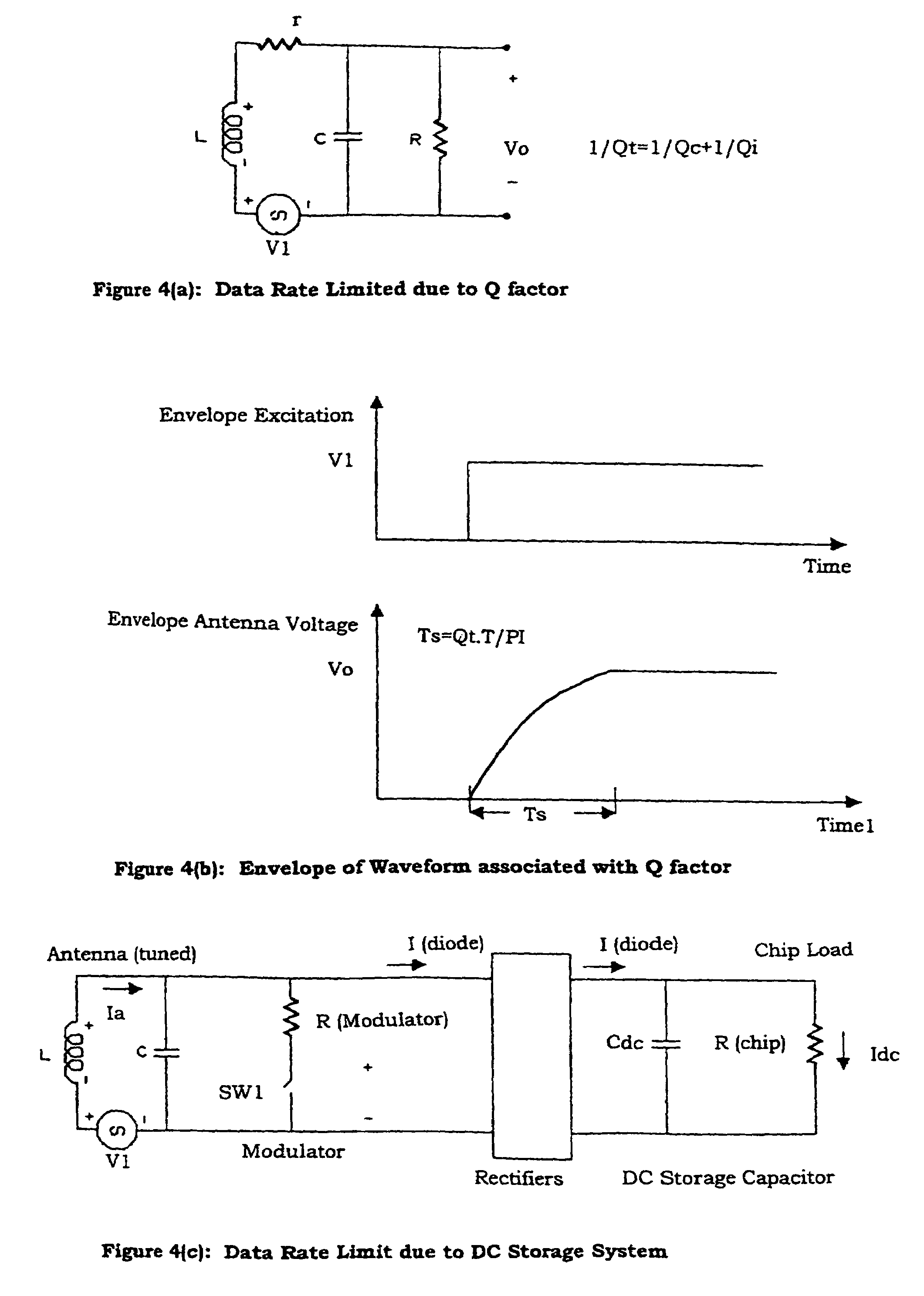
[0097]In the following explanation of the invention there is description using both the time and frequency domain methods. It will be appreciated by those skilled in the art that the time domain methods provide information on the transient behaviour of the invention while the frequency domain methods are used to interpret the AC electrical behaviour. It will also be appreciated that the terms “transponder” and “transceiver” are used interchangeably.

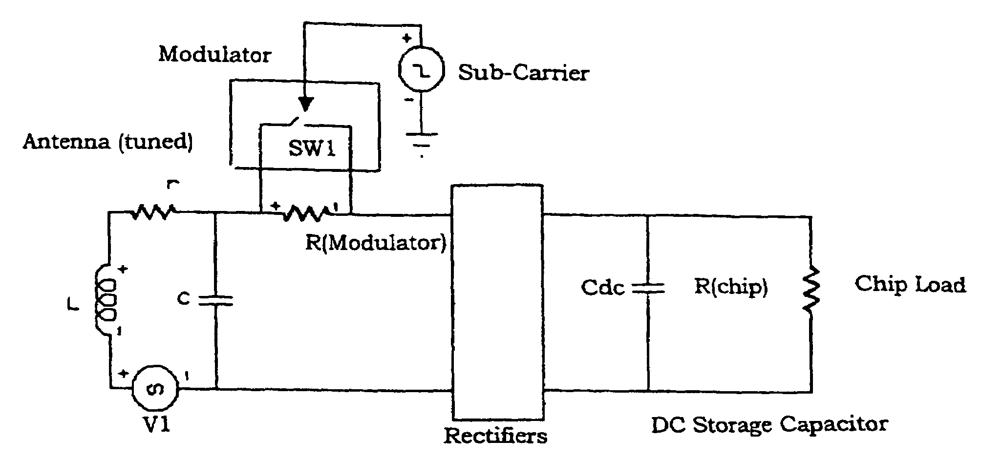
[0098]RFID transponders that incorporate a single antenna may be interrogated with an interrogating or exciting field. This field is received by the transponder's antenna and the voltage induced on the antenna may be rectified and used to power the transponder. It is necessary that the transponder be able to transmit messages back to its interrogator. For single antenna transponders the transmitted signal must be radiated off the same antenna that is used to receive the interrogating signal.

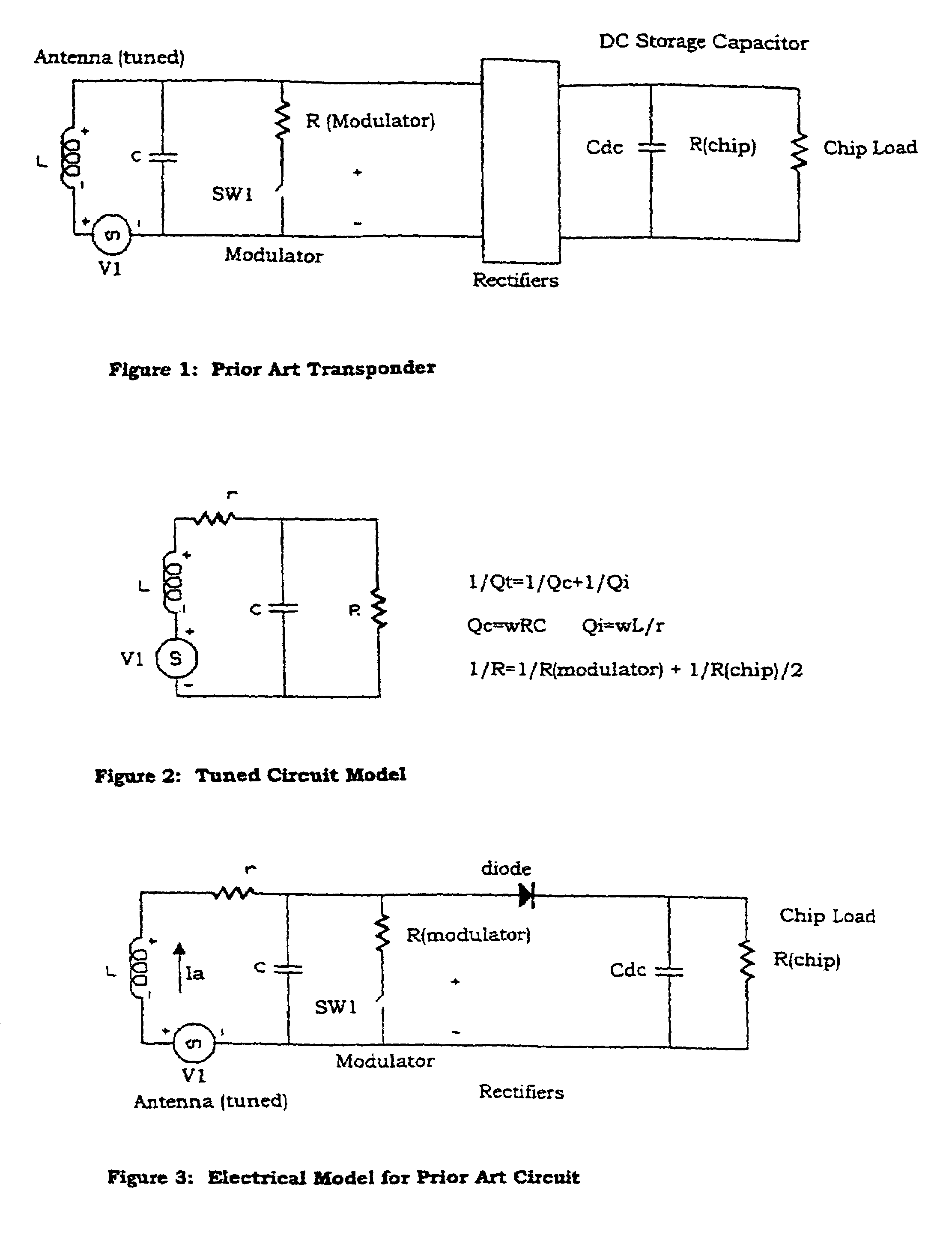
[0099]In prior art systems a resistance is provi...


PUM


Abstract

A transceiver according to the invention has application to a baggage handling system, amongst others, and includes an electrical circuit having a modulated series resistor, in the form of resistor R(modulator). Also included is a parallel switch SW1, which is placed between the antenna and a storage capacitor in the AC part of the circuit. In other embodiments the modulated series resistor, again in the form of resistor R(modulator) and parallel switch SW1, is placed between the antenna and the storage capacitor in the DC part of the circuit. Both circuits produce the same transmitted signal, although in practice the latter is simpler to implement due to its DC operating bias. In still further embodiments a modulated series resistor is placed between the antenna and the antenna's tuning capacitor.

Description

FIELD OF THE INVENTION[0001]The present invention relates to a transceiver.[0002]The invention has been developed primarily for the field of Radio Frequency Identification (RFID) and will be described hereinafter with reference to that application. It will be appreciated, however that the invention is also applicable to other fields. More particularly, the invention is applicable to receiving and transmitting data to and from a transponder using a single antenna, where the transmission may occur at any number of distinct frequencies. The invention has particular merit when applied to passive transponders. That is, transponders which derive their operating power from the received excitation or interrogation signal.BACKGROUND OF THE INVENTION[0003]In prior art systems passive RFID transponders have included a receiving antenna and a transmitting antenna. The need for separate antennae adds to the cost and complexity of the transponder. To address this limitation a number of single ant...

Claims


Application Information

Patent Timeline
Patent Type & Authority Patents(United States)
IPC IPC(8): H04B1/46H04B1/40H04B1/04H01Q11/12G01S13/74G01S13/75G01S13/76G01S13/79G06K7/00G06K19/07G06K19/077H04B1/59
CPCG01S13/74G01S13/75G06K7/0008G06K19/0723G06K19/07749G06K19/07758G06K19/07777
Inventor MURDOCH, GRAHAM
Owner SATO HLDG CORP
Why Eureka
Try Eureka