
Multi-feed dipole antenna and method

a dipole antenna and multi-feed technology, applied in the field of antennas, can solve the problems of side lobes and nulls, limited radiation pattern and impedance bandwidth of dipole antennas, and presumption of symmetry in the support structure on either side, and achieve the effect of wide pattern bandwidth and impedance bandwidth, and wider frequency rang

Inactive Publication Date: 2008-11-06
ANTENNASYS
View PDF19 Cites 2 Cited by
  • Summary
  • Abstract
  • Description
  • Claims
  • Application Information

AI Technical Summary

Benefits of technology

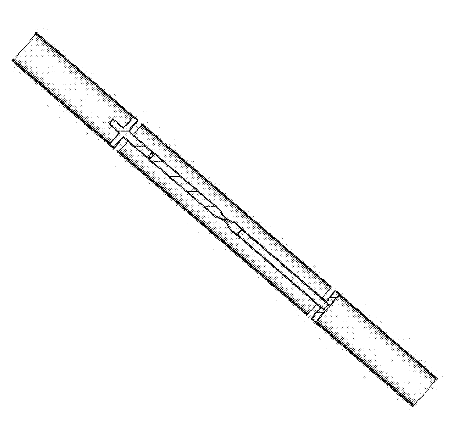
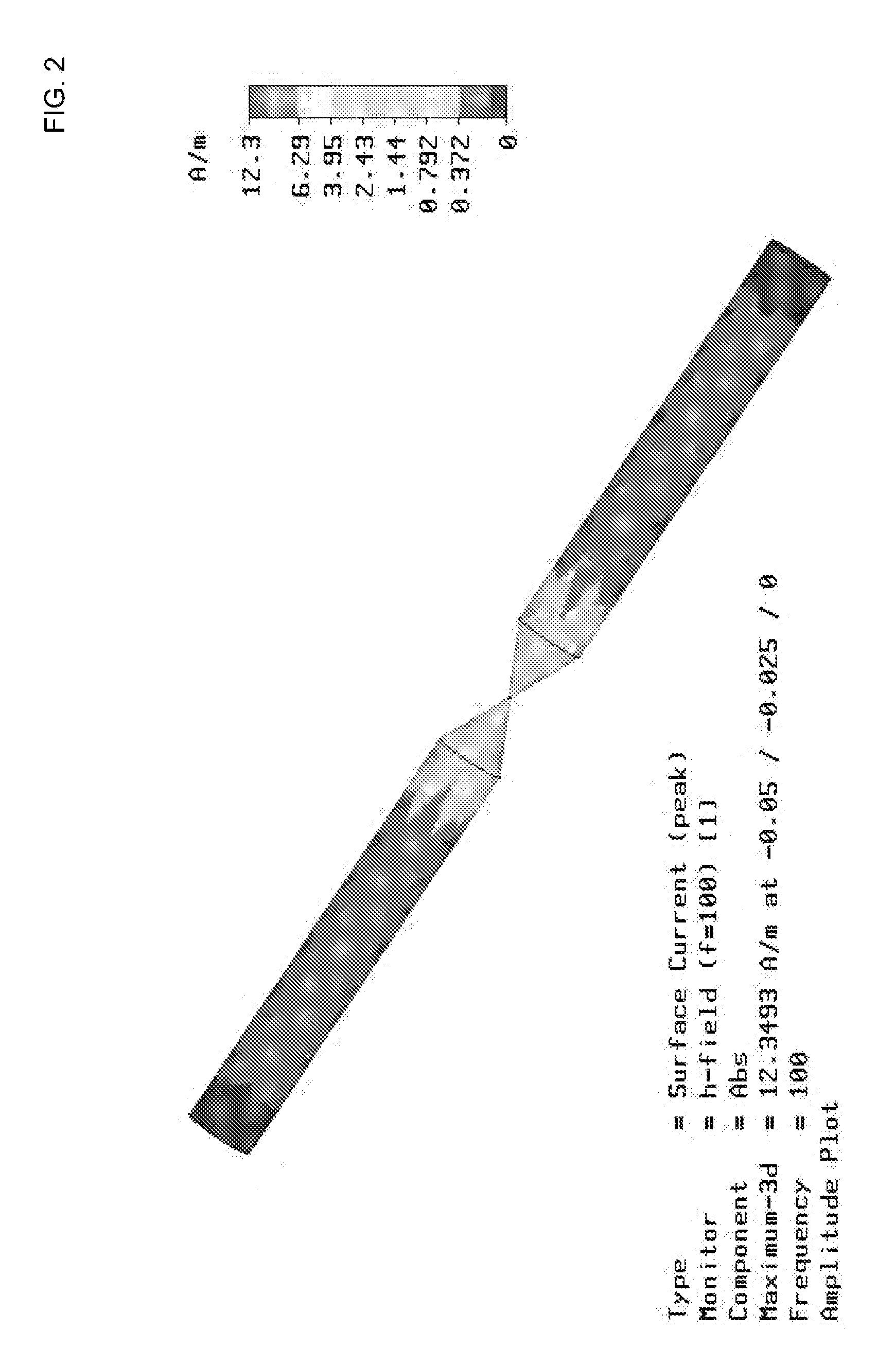
[0010]One or more embodiments of the invention are directed to a multi-feed dipole antenna and method. The apparatus provides a volumetrically efficient antenna with a very wide pattern bandwidth and impedance bandwidth. Driving the antenna at multiple locations provides for a half wavelength dipole antenna with a wider frequency range than any other known dipole antenna. The apparatus is constructed from brass or any other suitable conductor without requiring a dielectric loading material and without requiring direct coupling on the outside of the tubes. The apparatus utilizes a parasitic center tube with two end tubes that are driven by a collinearly mounted metal rod that is driven from the midpoint. Insulators hold the parasitic tube to the end tubes. The outside of the device radiates or receives electromagnetic energy while the inside of the device efficiently acts as a transmission line to deliver power between the central feedpoint and the outside of the apparatus. The parasitic tube allows for induced currents to flow on the surface of the tube which allow for operation of the multi-feed dipole antenna over a very wide frequency range.
[0013]Methods for manufacturing the antenna include coupling a coaxial cable to a top and bottom pin, coupling a center tube to the top tube and bottom tube via insulators and coupling the top and bottom tube to top and bottom pins conductively via top and bottom pin plates at offsets of zero or more units of measure from the junction of the center tube. The coaxial feed line may include one or more exterior ferrite beads to provide for decoupling of the antenna current from the outer surface of the feed line. The coaxial feed line may also include a quarter-wavelength transmission line transformer which may take the form of an electrical quarter-wavelength of 75-ohm coax between the antenna feed point and the 50-ohm transmission line departing the antenna. A non-conductive connection sleeve may be utilized to provide for a more stable interface between the top pin and bottom pin. Support caps may be utilized to provide support for the pins, and o-rings may be utilized between support caps at the tube junctions. Tube caps may be utilized to keep material out of the inner portions of the tubes. A tube mounting rod may be utilized to mount a rod to the antenna which allows for external mounting. The entire apparatus may be mounted inside a non-conductive tube for example to make the apparatus more durable. In doing so, a mounting rod may be utilized in the top tube for example that couples with the top pin to provide rigidity.

Problems solved by technology

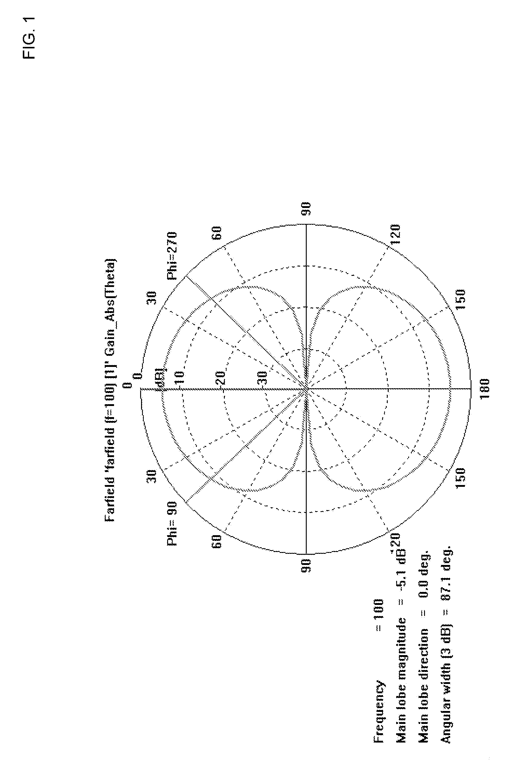
The pattern is said to “bifurcate” at the higher frequencies and results in a pattern that causes side lobes and nulls to appear where they would not appear at lower frequencies.
Dipole antennas are limited in terms of their radiation pattern and impedance bandwidth.
The main problems with this antenna are the presumption of symmetry in the support structure on either side of the antenna.
Also, the two feed points (gaps) are at a very high impedance and will present practical difficulties in impedance matching.
Further, the Pickles antenna is based upon very narrow-band structures such as quarter wave chokes, and is therefore not a wideband design.
The antennas described in these references fail to achieve maximum volumetric efficiency.
Johnson shows an open-sleeve dipole which does not make efficient use of a cylindrical volume, as the dipole elements are thin after exiting the sleeve.
Kraus shows a quarter wave sleeve monopole where the sleeve and the upper radiator are the same diameter, but the interior is not efficiently used for impedance matching.
Further, the quarter wave sleeve monopole requires a large ground plane for operation.
One problem with this antenna is the use of an asymmetrical feed structure.
Another problem is the use of heavy and expensive dielectric material to load the inside of the center tube so that it internally operates as a half-wavelength section.

Method used


Image

  • Multi-feed dipole antenna and method
  • Multi-feed dipole antenna and method
  • Multi-feed dipole antenna and method

Examples


Embodiment Construction

[0104]A multi-feed antenna and method will now be described. In the following exemplary description numerous specific details are set forth in order to provide a more thorough understanding of embodiments of the invention. It will be apparent, however, to an artisan of ordinary skill that the present invention may be practiced without incorporating all aspects of the specific details described herein. In other instances, specific features, quantities, or measurements well known to those of ordinary skill in the art have not been described in detail so as not to obscure the invention. Readers should note that although examples of the invention are set forth herein, the claims, and the full scope of any equivalents, are what define the metes and bounds of the invention.

[0105]One or more embodiments of the invention are directed to a multi-feed dipole antenna and method. The antenna provides wide radiation pattern bandwidth and wide impedance bandwidth. Driving the dipole at multiple l...


PUM

PropertyMeasurementUnit
dipole input impedanceaaaaaaaaaa
impedanceaaaaaaaaaa
impedanceaaaaaaaaaa

Abstract

A multi-feed dipole antenna and method. Provides a volumetrically efficient antenna with wide radiation pattern bandwidth and wide impedance bandwidth that are relatively independent. Driving the antenna at multiple locations provides for a half wavelength dipole antenna with a wider frequency range than any other known fat dipole of similar volume. The apparatus is constructed from brass or any other suitable metal without requiring dielectric loading and without requiring direct coupling on the outside of the tubes. The apparatus utilizes a parasitic center tube with two end tubes that are driven by a collinearly mounted metal rod that is driven from the midpoint. Insulators hold the parasitic tube to the end tubes. The parasitic tube allows for induced currents to flow on the surface of the tube which allow for operation of the dipole over a wide frequency range.

Description

[0001]This application claims the benefit of U.S. Provisional Patent Application Ser. No. 60 / 890,840, filed 21 Feb. 2007, the specification of which is hereby incorporated herein by reference.BACKGROUND OF THE INVENTION[0002]1. Field of the Invention[0003]Embodiments of the invention described herein pertain to the field of antennas. More particularly, but not by way of limitation, one or more embodiments of the invention enable a multi-feed dipole antenna and method covering a wide frequency band.[0004]2. Description of the Related Art[0005]One of the simplest antennas is a dipole antenna. The length of a typical dipole antenna generally approximates one half-wavelength of a desired transmit / receive frequency. The radiation pattern provided by a dipole antenna is limited when the frequency of the signal at the antenna is high enough to assert harmonic modes in the current distribution. The pattern is said to “bifurcate” at the higher frequencies and results in a pattern that causes...

Claims


Application Information

Patent Timeline
Patent Type & Authority Applications(United States)
IPC IPC(8): H01Q9/16H01P11/00
CPCH01Q9/22Y10T29/49016H01Q9/28
Inventor WEBB, SPENCER L.
Owner ANTENNASYS
Learn More