System and method for input current shaping in a power converter
What is AI technical title?
AI technical title is built by Patsnap AI team. It summarizes the technical point description of the patent document.
a power converter and input current technology, applied in the field of power converters, can solve the problems of inability to deliver electrical power with high power factor over a broad or full range of input voltage, conventional power converters require complex circuitry, and considerable stability efforts, and achieve the effect of high power factor
Inactive Publication Date: 2009-06-16
DIALOG SEMICONDUCTOR INC
View PDF6 Cites 8 Cited by
Summary
Abstract
Description
Claims
Application Information
AI Technical Summary
This helps you quickly interpret patents by identifying the three key elements:
Problems solved by technology
Method used
Benefits of technology
Benefits of technology
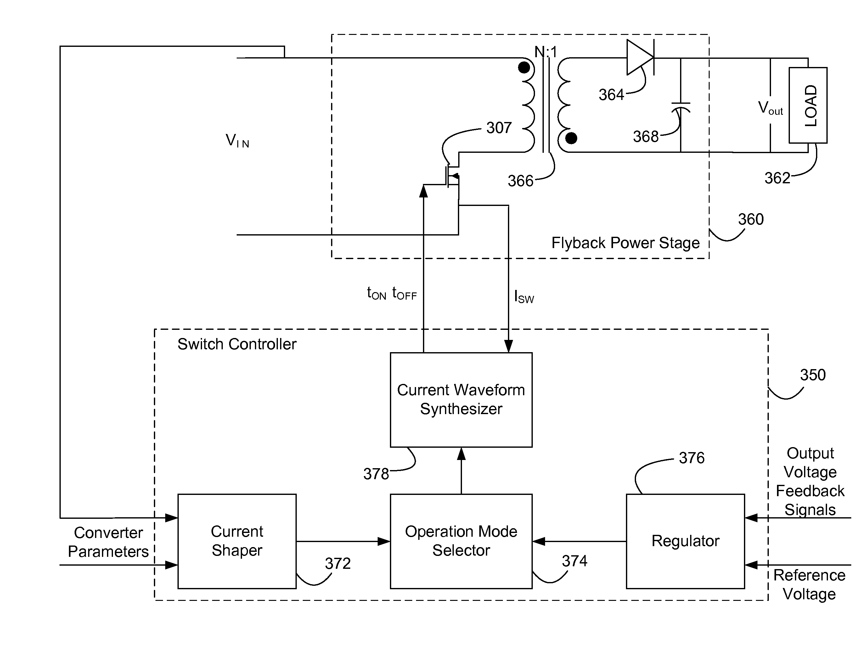
[0012]The power converter of the present invention and the method for controlling the power converter can transfer electrical power from a power source to a load with a high power factor over a wide range of input voltage with the input current shaped by the reference shape of peak current. Peak current switching ensures that the peak input current to the power converter does not exceed the peak current values prescribed for the corresponding phase of the input voltage to the power converter according to the reference shape of peak current, and thus the shape of the input current is determined by the reference shape. The power converter and the method for controlling the power converter of the present invention are compatible with different topologies of power converters, including flyback power converters and boost-type power converters, providing an input current shaped by the reference waveform, to achieve regulation of output voltage with high power factor over a wide range of input voltage.
Problems solved by technology
These conventional power converters may work well in a given range of input voltage levels, but none of these conventional power converters can deliver electrical power with high power factors over a broad or full range of input voltage.
The implementation of these conventional power converters requires complex circuitry further requiring considerable efforts to stabilize them.
Furthermore, the conventional power converters have a particular topology, but none of the control strategy for these conventional power converters may be used with different topologies of power converters.
Method used
Image
Click on the blue label to locate the original text in one second.
Reading with bidirectional positioning of images and text.
Examples
Embodiment Construction
[0033]The embodiments of the present invention will be described below with reference to the accompanying drawings. Like reference numerals are used for like elements in the accompanying drawings.
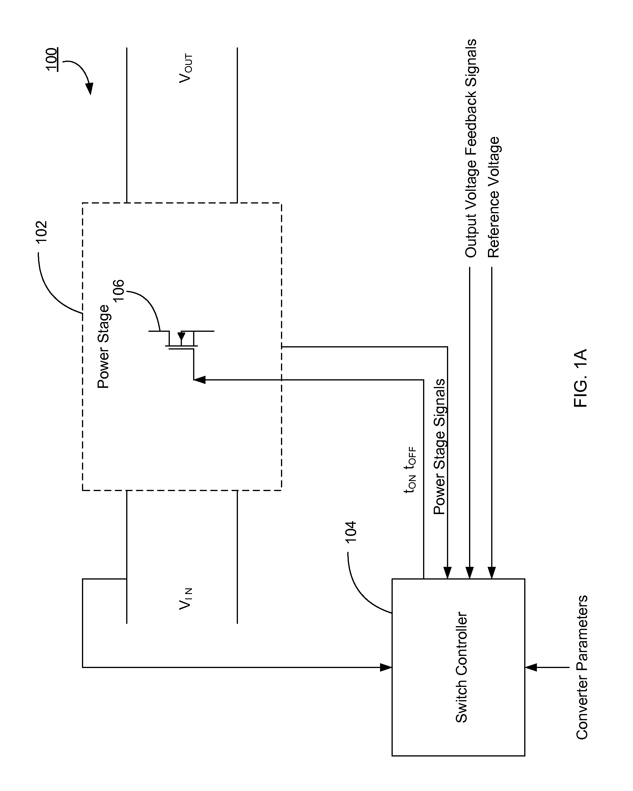
[0034]FIG. 1A is a diagram of the power converter 100 according to one embodiment of the present invention. The power converter 100 includes a power stage 102 and a switch controller 104. The power stage 102 receives full-wave rectified input voltage VIN from an electrical power source (not shown) and transfers power to a load (not shown) with an output voltage VOUT by turning the switch 106 on and off to couple or decouple the input voltage VIN to or from the output. The switch 106 is a conventional MOSFET switch but any other type of switch or any number of switches may be used.
[0035]The switch controller 104 generates pulses to open or close the switch 106 so that the power stage 102 can deliver electrical power with high power factor, e.g., 0.90 or more. In one embodiment, the switch co...
PUM
Abstract
A power converter delivers electrical power from an electrical power source to a load according to a plurality of operation modes, where at least one of the operation modes is a peak current switching mode. Under the peak current switching mode, a switch controller controls the switch in the power converter to be kept on until the current through the switch reaches a peak current value corresponding to a given phase of the input voltage signal to the power converter. The peak current values have a reference shape, which may be a trapezoidal. The power converter may have any topology, such as a flyback-type power converter or a boost-type power converter.
Description
CROSS-REFERENCE TO RELATED APPLICATIONS[0001]This application is a divisional application under 35 U.S.C. §121 of, and claims priority under 35 U.S.C. §120 from, U.S. patent application Ser. No. 10 / 880,221 entitled “System and Method for Input Current Shaping in a Power Converter,” filed on Jun. 28, 2004 now U.S. Pat. No. 7,433,211, which is a continuation-in-part application of, and claims priority under 35 U.S.C. §120 from, U.S. patent application Ser. No. 10 / 610,977, entitled “System and Method for Input Current Shaping In a Power Converter,” filed on Jun. 30, 2003, now issued as U.S. Pat. No. 6,944,034, both of which are incorporated by reference herein in their entirety. This application is also related to U.S. patent application Ser. No. 12 / 146,261, entitled “System and Method for Input Current Shaping in a Power Converters” filed on Jun. 25, 2008.TECHNICAL FIELD[0002]The present invention relates generally to a power converter, and more specifically, to a system and method fo...
Claims
Application Information
Patent Timeline
Application Date:The date an application was filed.
Publication Date:The date a patent or application was officially published.
First Publication Date:The earliest publication date of a patent with the same application number.
Issue Date:Publication date of the patent grant document.
PCT Entry Date:The Entry date of PCT National Phase.
Estimated Expiry Date:The statutory expiry date of a patent right according to the Patent Law, and it is the longest term of protection that the patent right can achieve without the termination of the patent right due to other reasons(Term extension factor has been taken into account ).
Invalid Date:Actual expiry date is based on effective date or publication date of legal transaction data of invalid patent.
Patent Type & AuthorityPatents(United States)
IPC IPC(8): H02M3/335
CPCH02M1/4225H02M1/4258Y02B70/126Y02B70/10
InventorCOLLMEYER, ARTHUR J.SHTEYNBERG, ANATOLYZHENG, JUNJIEKING, PAUL F.WONG, DICKSON T.RODRIGUEZ, HARRY

