Quick change tool holder

a tool holder and quick-change technology, which is applied in the field of quick-change adaptor systems, can solve the problems of affecting the operation of the tool holder, the inability to use a dedicated machining instrument, and the significant down time of the machining instrument every time the tool is to be changed, and achieves the effect of constricting the tool and reducing the force of the tool

Inactive Publication Date: 2009-06-23
AMERICAN FLASHLIGHT TIP
View PDF17 Cites 26 Cited by
  • Summary
  • Abstract
  • Description
  • Claims
  • Application Information

AI Technical Summary

Problems solved by technology

Ensuring this concentricity can make placing a tool in the tapered recess a delicate and time-consuming process.
And due to the cost of precision machining instruments, it is impractical to utilize a dedicated machining instrument for working with each size of tool commonly found in a typical machine shop.
Thus, many different-sized tools will often be swapped in and out of a given machining instrument, making the significant down time of the machining instrument every time the tool is to be changed costly to the owner of said instrument.
This type of tool holder configuration was complex, and required removal of the tapered recess from the machining instrument each time a different-sized tool was to be secured thereto.
The significant changeover times associated with this type of configuration creates long downtimes that are costly to the machine's owner.
Again, such configurations were costly, and required complex control circuitry to select and install the proper tool to be used for machining a specific workpiece.

Method used


Image

  • Quick change tool holder
  • Quick change tool holder
  • Quick change tool holder

Examples


Embodiment Construction

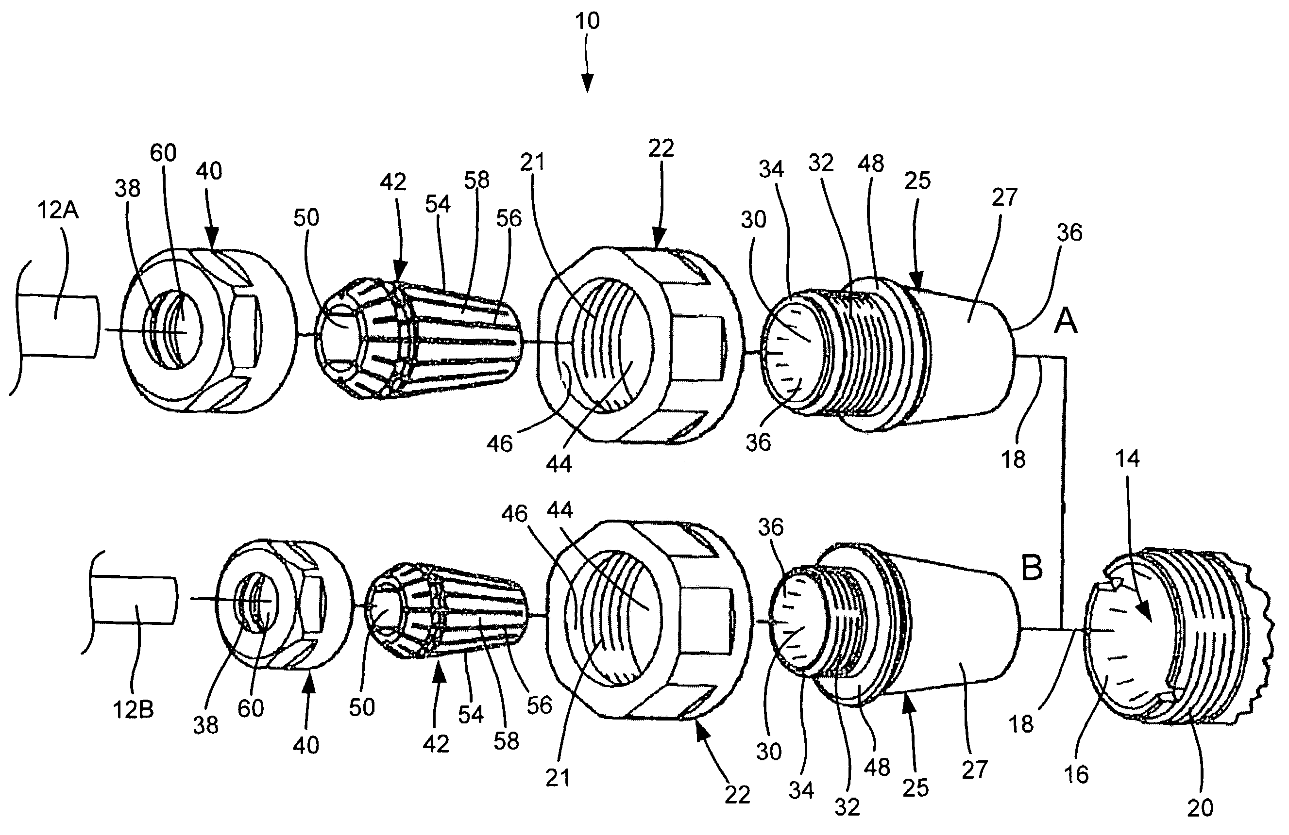
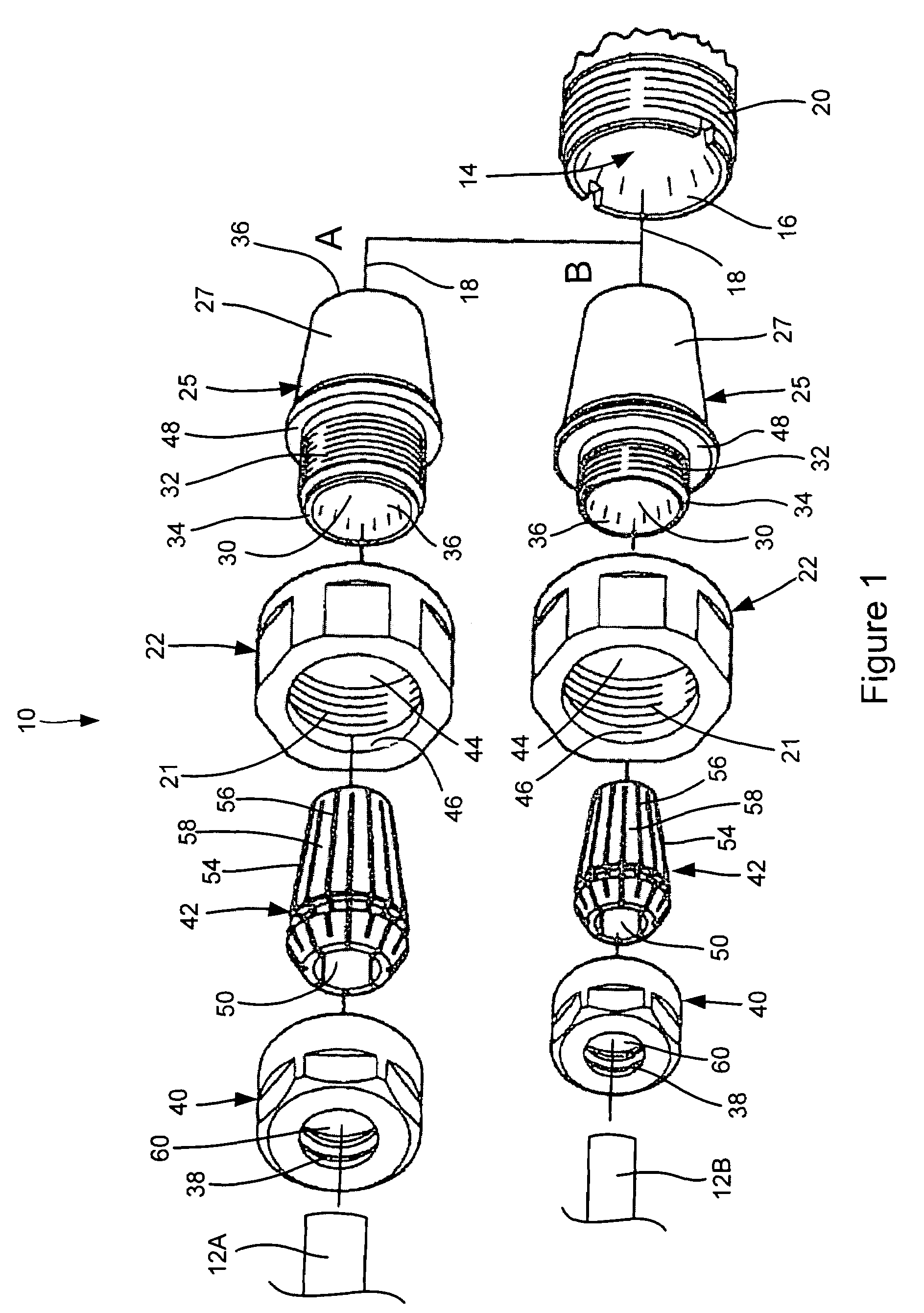
[0012]Certain terminology is used herein for convenience only and is not to be taken as a limitation on the present invention. Relative language used herein is best understood with reference to the drawings, in which like numerals are used to identify like or similar items. Further, in the drawings, certain features may be shown in somewhat schematic form.

[0013]FIG. 1 provides an exploded view of two illustrative embodiments of a quick-change tool-holding system 10 in accordance with the present invention for securing at least a portion of a tool 12A or 12B (both of which are generally referenced herein by numeral 12) within a primary tapered recess 14 provided adjacent to an end of a rotatable spindle (not shown) of a machining instrument. Although the embodiments discussed below refer to the primary tapered recess 14 as being located adjacent to the end of a rotatable spindle, it is to be understood that the tool-holding system 10 of the present invention can be compatible with a ...


PUM

PropertyMeasurementUnit
taper angleaaaaaaaaaa
interior dimensionsaaaaaaaaaa

Abstract

A quick-change tool-holding method and system for securing a tool within a primary tapered recess is disclosed. The tool-holding system includes an adaptor having a tapered exterior that closely approximates interior dimensions of the tapered recess to fit snugly within the tapered recess. The adaptor defines a secondary interior tapered recess and includes an exterior threaded portion about an aperture leading into the secondary tapered recess. A threaded fastener is also provided to include a threaded portion that is cooperable with threads provided adjacent to the primary tapered recess to secure the adaptor therein, as well as an aperture through which at least a portion of the exterior threaded portion of the adaptor extends when the adaptor is secured within the primary tapered recess by the threaded fastener. A collet comprising a plurality of slits formed therein is provided to allow the collet to elastically deform and constrict the tool when placed within an internal passage defined by the collet. An end cap with threads that are cooperable with the exterior threaded portion of the adaptor is included to urge the collet into the secondary tapered recess resulting in a constricting force on the tool within the collet's internal passage.

Description

FIELD OF THE INVENTION[0001]The present invention is directed generally to a tool holder, and more specifically to a quick-change adaptor system for coupling a plurality of differently-sized tools to a machining instrument.BACKGROUND OF THE INVENTION[0002]Traditionally, milling machines, lathes and other machining instruments have been provided with a tapered recess at the end of a rotatable spindle or elsewhere on a machine for receiving a tool such as a bit for performing milling or other operations on a workpiece. Such configurations typically include an elastically deformable collet that is placed within the tapered recess to securely fix the tool within the tapered recess. The collet also maximizes the concentricity between the tapered recess and the tool being secured therein. The force imparted on the collet by the walls of the tapered recess as the collet is urged inwardly into the tapered recess constricts the collet about a tool partially inserted into the hollow cavity of...

Claims


Application Information

Patent Timeline
Patent Type & Authority Patents(United States)
IPC IPC(8): B23Q13/00B23B31/00B23C5/26
CPCB23B31/20B23B51/123B25G3/30Y10T279/3418Y10T279/3406Y10T409/309408Y10T279/17299Y10T279/17504Y10T408/957Y10T483/1864B23B31/20125
Inventor WALTERS, DANIEL
Owner AMERICAN FLASHLIGHT TIP
Why Eureka
Try Eureka