
Adjusting voltage delivered to disk drive circuitry based on a selected zone

a voltage adjustment and circuit technology, applied in the field of disk drives, can solve the problems of reducing the utility of the mobile mode, affecting the performance of the disk drive at lower speeds, and difficulty in maintaining a constant fly-height at different speeds

Inactive Publication Date: 2009-06-23
WESTERN DIGITAL TECH INC
View PDF82 Cites 150 Cited by
  • Summary
  • Abstract
  • Description
  • Claims
  • Application Information

AI Technical Summary

Problems solved by technology

First, the performance of a disk drive at lower speeds is significantly impaired, reducing the utility of the mobile mode.
Second, there is the difficulty of maintaining a constant fly-height at different speeds.
Finally, operating a disk drive at different speeds presents complex electrical engineering issues.

Method used


Image

  • Adjusting voltage delivered to disk drive circuitry based on a selected zone
  • Adjusting voltage delivered to disk drive circuitry based on a selected zone
  • Adjusting voltage delivered to disk drive circuitry based on a selected zone

Examples


Embodiment Construction

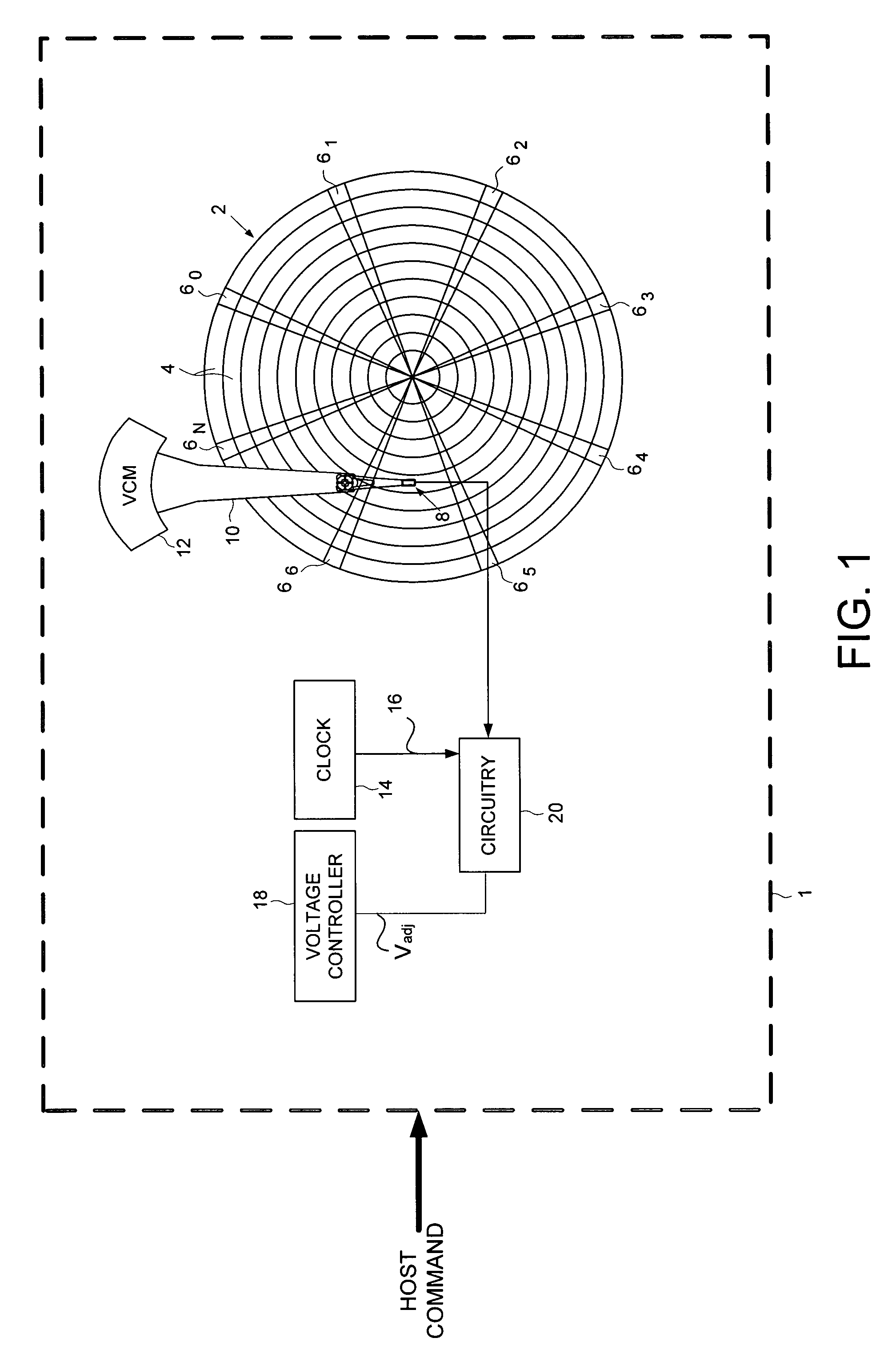
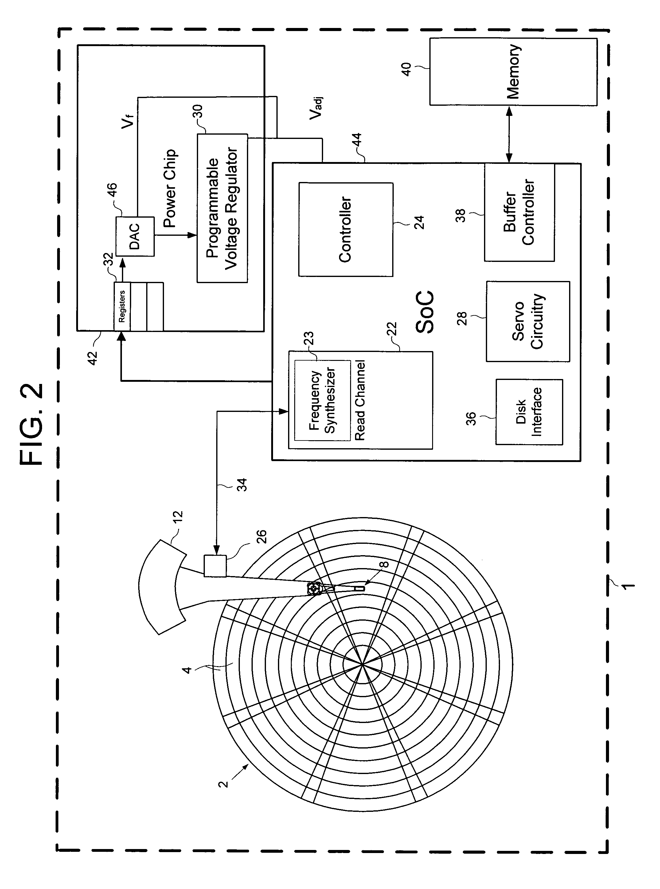
[0015]Referring to FIG. 1, according to one embodiment of the present invention, disk drive 1 comprises a disk 2 having a plurality of zones 4, wherein a first zone comprises data recorded at a first data rate, a head 8 actuated over the disk 2 for generating a signal representing the data, and a voice coil motor 12 configured to actuate the head 8 over the disk 2 via an actuator arm 10. The disk drive 1 further comprises a clock 14 configured to generate a timing signal 16 having a timing frequency and configured to adjust the timing frequency in response to the first data rate, circuitry 20 responsive to the timing frequency, and a voltage controller 18 configured to adjust a supply voltage Vadj provided to the circuitry 20 in response to the first data rate. Although a preferred embodiment of the present invention is described herein in terms of a magnetic disk drive, it may be understood that the methods, circuitry and devices described herein may also be implemented in other di...


PUM

PropertyMeasurementUnit
timing frequencyaaaaaaaaaa
voltageaaaaaaaaaa
supply voltageaaaaaaaaaa

Abstract

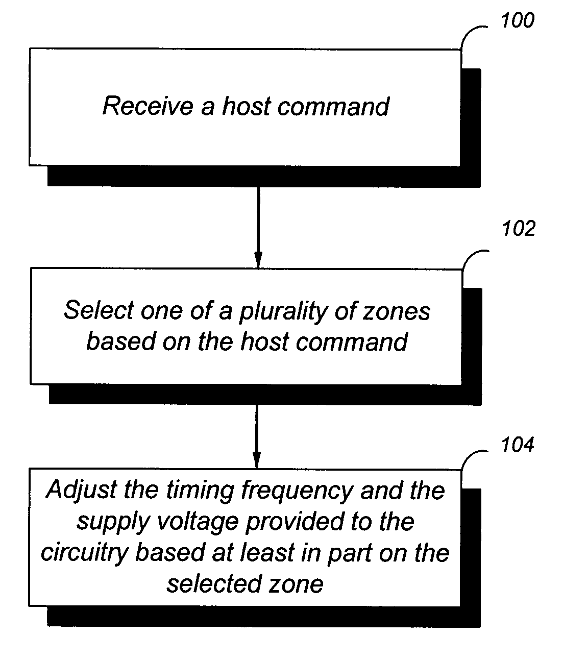
A disk drive includes a disk comprising a plurality of zones, a clock for generating a timing signal having a timing frequency, a voltage controller for providing a supply voltage, and circuitry coupled to the supply voltage and responsive to the timing frequency. Power may be conserved by receiving a host command; selecting one of the plurality of zones based on the host command; and adjusting the timing frequency and the supply voltage provided to the circuitry based at least in part on the selected zone.

Description

BACKGROUND[0001]1. Field[0002]This invention relates to disk drives and, more particularly, to electrical power supplied to disk drive circuitry.[0003]2. Description of the Related Art[0004]Magnetic disk drives are conventionally designed to store large volumes of data on a plurality of disks mounted on a spindle assembly. In general, each disk includes two disk surfaces capable of storing data. On each disk surface, user data is divided into groups of sectors and stored in concentric circular tracks located between an outside diameter and inside diameter of the disk. Embedded servo information is recorded in servo sectors located in radially continuous narrow wedges along the disk surface.[0005]In order to maximize the data recorded on each disk surface, it is desirable to use zone recording techniques. According to such techniques, the rate or frequency at which data is written to a disk surface increases from the inner tracks to the outer tracks to compensate for the fact that da...

Claims


Application Information

Patent Timeline
Patent Type & Authority Patents(United States)
IPC IPC(8): G11B5/02
CPCG11B5/012G11B19/02
Inventor KUPFERMAN, HANAN
Owner WESTERN DIGITAL TECH INC
Learn More