Raindrop sensor for an irrigation system

a technology of irrigation system and sensor, which is applied in the field of raindrop sensor for irrigation system, can solve the problems of unreliable and inconvenient methods, over-watering and under-watering of landscaping,

Inactive Publication Date: 2009-06-30
TORO CO THE
View PDF35 Cites 46 Cited by
  • Summary
  • Abstract
  • Description
  • Claims
  • Application Information

AI Technical Summary

Problems solved by technology

However, user programmed irrigation schedules often require additional environmental information to accurately provide a desired amount of water to the irrigation zone.
Often this method proves to be unreliable and inconvenient due to operator inconsistencies.
This may cause over-watering and under-watering of the landscaping.

Method used


Image

  • Raindrop sensor for an irrigation system
  • Raindrop sensor for an irrigation system
  • Raindrop sensor for an irrigation system

Examples


Embodiment Construction

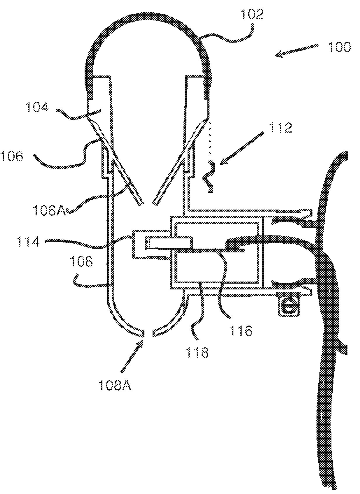
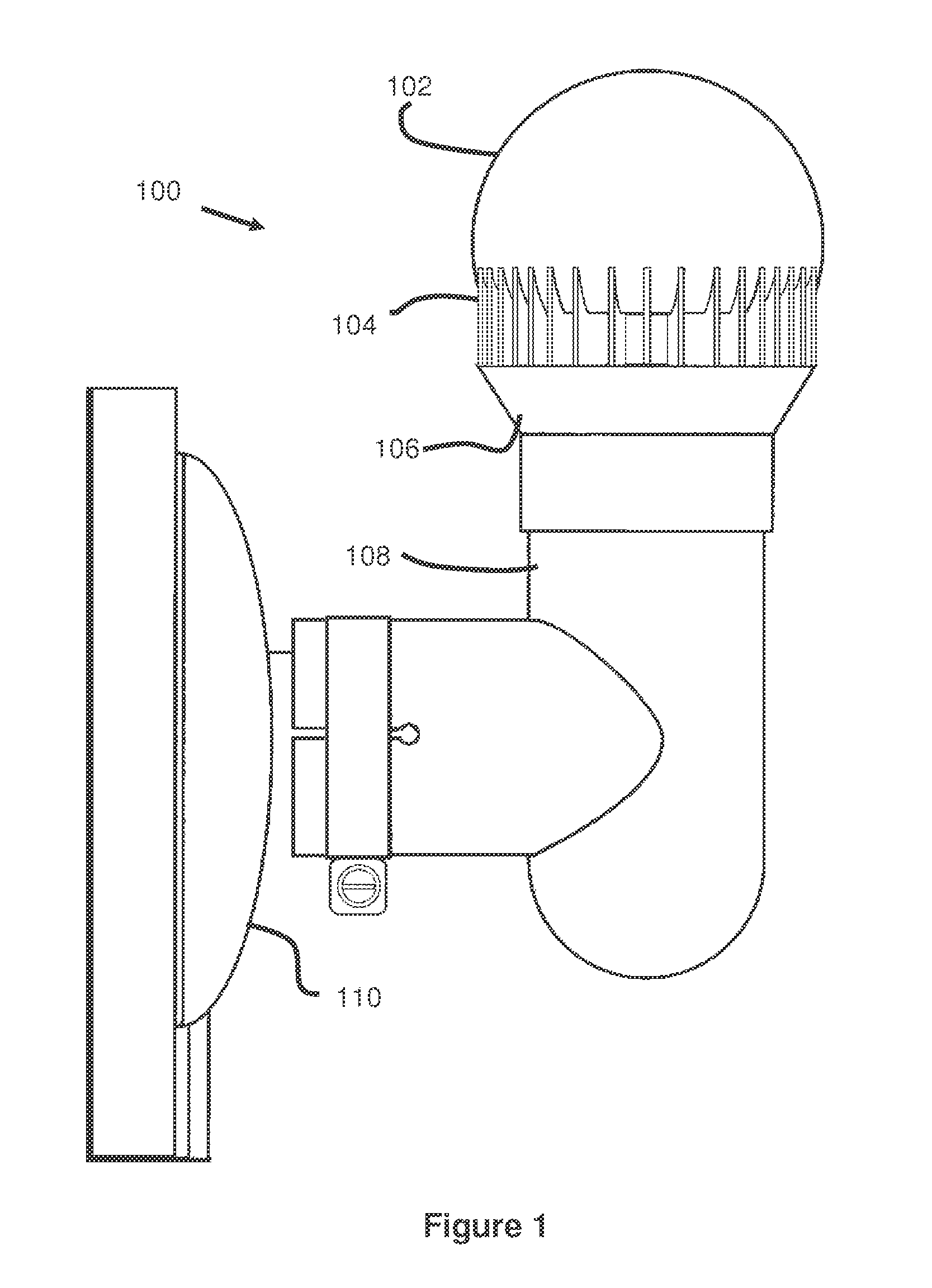
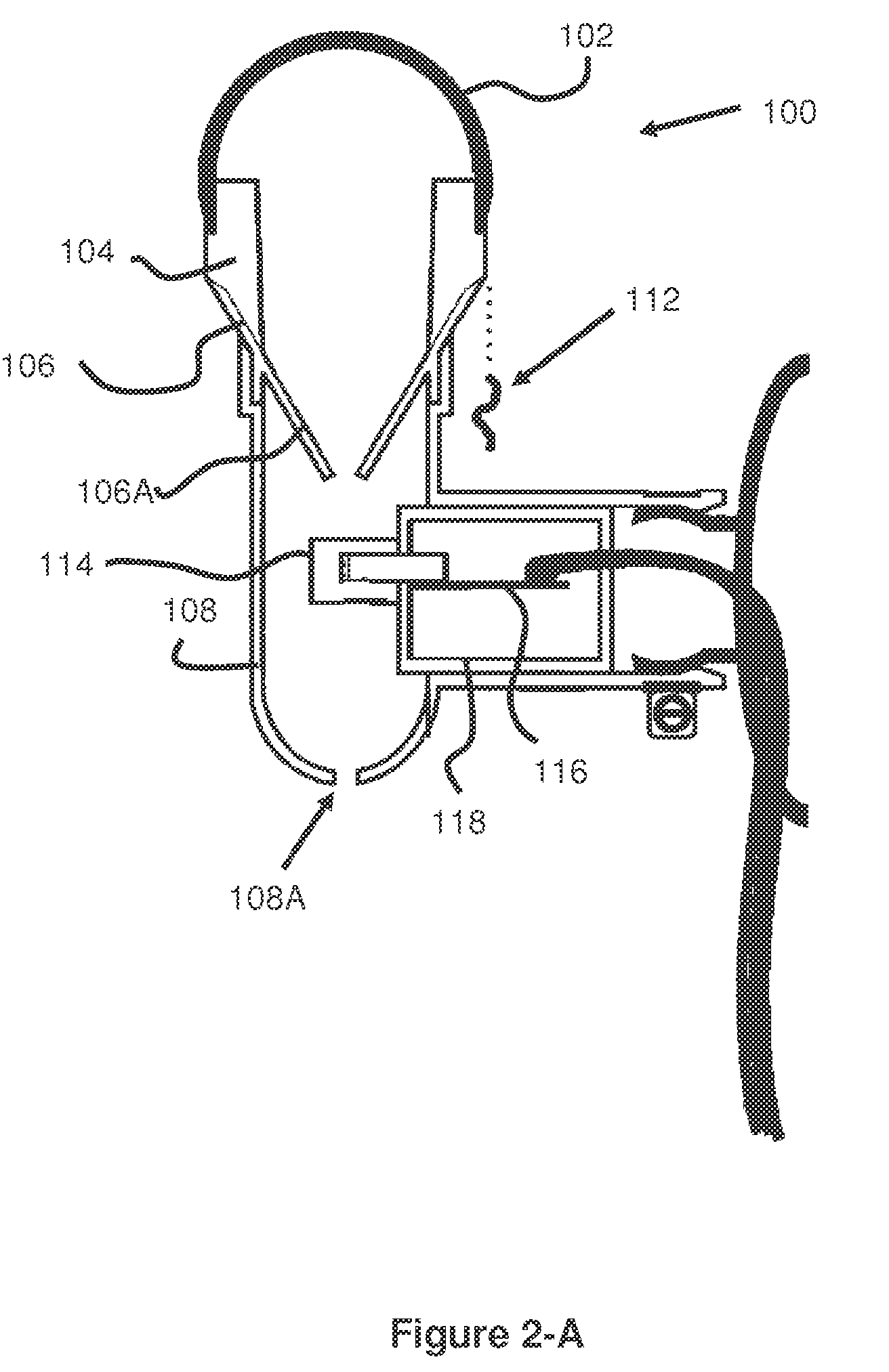
[0015]FIGS. 1, 2-A and 2-B illustrates a preferred embodiment of a rain sensor 100 according to the present invention that couples to an irrigation controller (not shown) to interrupt an irrigation schedule. More specifically, the rain sensor 100 measures rainfall or other precipitation by counting individual drops of water.

[0016]As seen in these figures, the rain sensor 100 includes a top member 102 having a rounded or spherical shape. The top member 102 is supported by a plurality of fins 104 positioned around at least a portion of the circumference of the top member 102. The fins 104 are also fixed to a collecting member 106 which forms a funnel or conical shaped region 106A in the interior of the body 108 of the rain sensor 100. A sensor 114 is fixed beneath a bottom opening of the collecting member 106 by a bracket 118 and is further connected to a circuit board 116.

[0017]In operation, precipitation strikes the top member 102, moving down the side of the top member 102 to the f...


PUM


Abstract

The present invention describes a rain sensor that counts water drops with a microcontroller. After a predetermined threshold of water drops have been counted, the rain sensor interrupts an irrigation schedule of an irrigation controller.

Description

RELATED APPLICATIONS[0001]This application claims priority to U.S. Provisional Application Ser. No. 60 / 821,797 filed Aug. 8, 2006, entitled Rain Drop Sensor for an Irrigation System, the contents of which are hereby incorporated by reference.BACKGROUND OF THE INVENTION[0002]Automatic irrigation systems such as those employed for landscape and agricultural watering are well known in the art. Typical irrigation systems use a means of controlling the watering cycles via a programmable irrigation controller.[0003]However, user programmed irrigation schedules often require additional environmental information to accurately provide a desired amount of water to the irrigation zone. More specifically, irrigation schedules more accurately maintain a desired soil moisture level when they are responsive to precipitation, high wind and freezing temperature situations.[0004]The simplest method of suspending an automatic watering cycle in an irrigation system involves the operator manually cancel...

Claims


Application Information

Patent Timeline
Patent Type & Authority Patents(United States)
IPC IPC(8): G01W1/00
CPCA01G25/167G01W1/14
Inventor RUNGE, THOMAS H.HOPKINS, LARRY KENTGRUNDY, MICHAEL JAMES
Owner TORO CO THE
Why Eureka
Try Eureka