Synthetic resin container having improved shape stability

a synthetic resin and container technology, applied in the direction of rigid containers, large containers, packaging, etc., can solve the problems of inevitably reducing the rigidity of the container to cope with such a demand, the container's type of synthetic resin container has a relatively low mechanical strength against external forces, and the container's gripping portion is inevitably deformed, so as to achieve the required shape stability and avoid the effect of lowering the rigidity of the container

Inactive Publication Date: 2009-06-30
YOSHINO KOGYOSHO CO LTD
View PDF27 Cites 24 Cited by
  • Summary
  • Abstract
  • Description
  • Claims
  • Application Information

AI Technical Summary

Benefits of technology

[0010]It is therefore an object of the present invention to provide a synthetic resin container capable of solving the above-mentioned problems of the prior art and effectively avoiding lowering of the rigidity of the container regardless of its thin-walled nature, to thereby exhibit a required shape stability of the container.

Problems solved by technology

This type of synthetic resin container has a relatively low mechanical strength against external forces.
Therefore, when the container is gripped at its main body portion for pouring the content out of the container, the container inevitably undergoes deformation at its gripped portion.
Furthermore, there is an increasing demand for thin-walled (or light-weighted) containers so as to reduce the resin amount to be used per one container from a standpoint of effective utilization of resources and reduction in the amount of wastes, resulting in a situation where the rigidity of the container is inevitably further lowered to deal with such a demand.
Meanwhile, synthetic resin containers have a relatively low thermal strength, and particularly, containers made of PET resin (polyethylene terephthalate resin) have a limitation on the filling temperature of contents, which must be not higher than approximately 85 to 87° C. Thus, when the contents at temperatures exceeding such a temperature range is filled into the containers, the containers are inevitably deformed due to heat shrinkage thereof.
However, when this type of targeted container is thin-walled (or light-weighted) so as to reduce the used resin amount (for example, when the used resin amount is reduced from approximately 69 grams to 55 grams or less, in the case of a 2-liter container), the lower region of the container main body portion tends to bulge outwardly due to the self-weight (i.e., hydraulic head) of the contents and due to the affection of heat of the contents, thereby making it difficult to retain the initial shape of the container.
Although it is effective to form lateral ribs on a container main body portion so as to retain the outer shape of the container, the ribs may warp due to affection of heat because the container is thin-walled, thereby failing to effectively exhibit the reinforcing function of the ribs.

Method used


Image

  • Synthetic resin container having improved shape stability
  • Synthetic resin container having improved shape stability
  • Synthetic resin container having improved shape stability

Examples


first embodiment

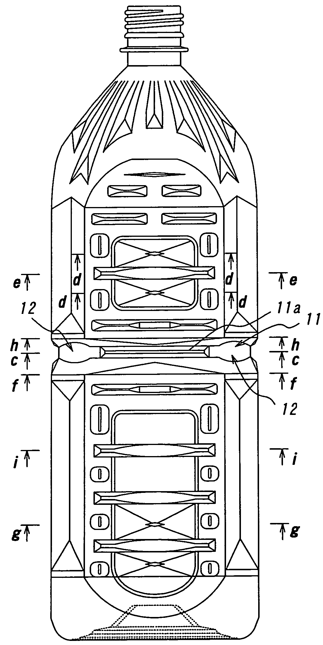
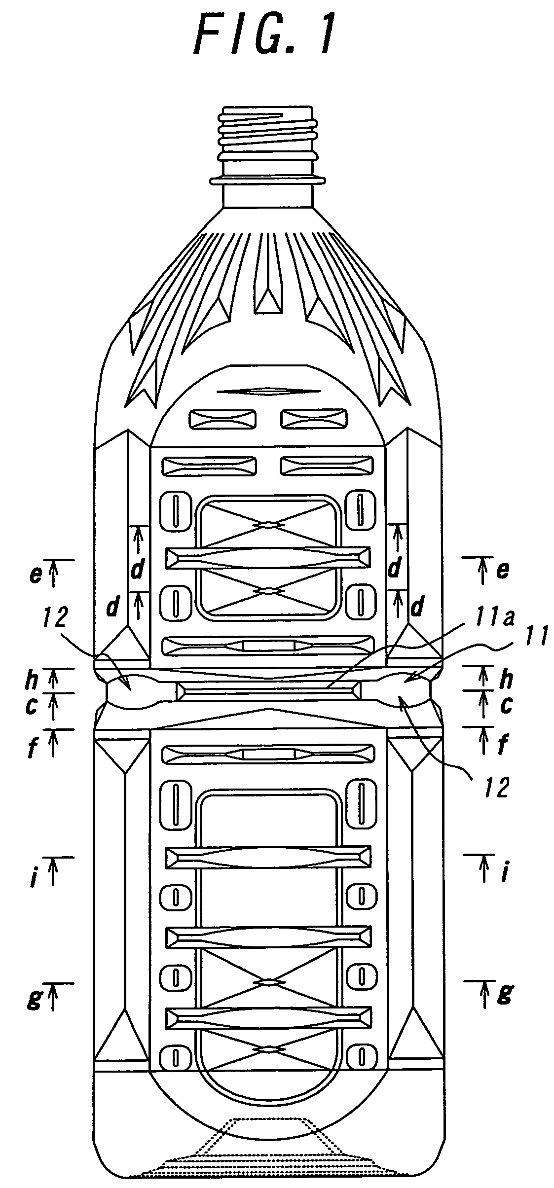
[0036]FIG. 1 through FIG. 4 show a synthetic resin container according to the present invention. This container has a filling volume of 2.0 liters and is formed in a substantially quadrilateral cross-sectional shape. Reference numeral 11 denotes a waist which divides a main body portion of the container into upper and lower parts. This waist 11 comprises an annular groove 11a surrounding the main body portion in a manner to become convex toward the interior of the container.

[0037]Reference numerals 12 denotes reinforcing ribs, respectively, each having has a level higher than a groove bottom of the annular groove 11a and lower than the surface of the main body portion. Each reinforcing rib is formed into an arcuate shape at its outer periphery. These reinforcing ribs 12 are provided at four corners of the main body portion of the container in the present embodiment, respectively.

[0038]Although the waist formed by simply recessing the container main body portion and thereby dividing ...

second embodiment

[0045]FIG. 5 and FIG. 6 show a synthetic resin container according to the present invention. Reference numeral 21 denotes a container body, and reference numeral 22 denotes a mouth portion integral with the container body 21. Furthermore, reference numeral 23 denotes a groove portion for dividing the container body 21 into upper and lower parts to thereby enhance the rigidity of the container, and reference numerals 24 denotes pressure-reduction absorbing panels, respectively. Each pressure-reduction absorbing panel 24 has a function for preventing a shape deformation of the container due to a volume change thereof as a result of cooling of the contents therein.

[0046]Reference numeral 25 denotes reinforcing lateral ribs formed at the main body portion of the container so as to extend across the pressure-reduction absorbing panels 24, respectively. Each lateral rib 25 has a concave portion 25a at a central region (i.e., the central region in the longitudinal direction) of the lateral...

third embodiment

[0051]FIG. 7 shows a synthetic resin container according to the present invention. In this embodiment, the region around each longitudinal rib 26 is formed as a concave portion 28 which is lower than surface of the container main body portion such that the contour shape of the longitudinal rib 26 is embossed upon molding the container to thereby further enhance the reinforcing effect near the corner portion of the container, while each lateral rib 25 is made to have a reduced length such that the opposite ends thereof are short of the associated pillars 27, respectively. Such a constitution ensures that the buckling strength is further enhanced in the container having a quadrilateral cross-section, and the restoring ability of the container after deformation is further improved.

[0052]When containers are produced by adopting a polyethylene terephthalate resin as the resin for the container and conducting two times of biaxial-stretching blow molding before and after an intermediate of...


PUM


Abstract

The synthetic resin container according to the present invention has a waist dividing a container main body portion into upper and lower parts, wherein the waist is formed on an annular groove surrounding the main body portion to as to be convex toward the interior of the container. The annular groove has reinforcing ribs with a level higher than a groove bottom of the annular groove and lower than the surface of the main body portion. The container main body portion includes reinforcing lateral ribs each having a concave portion which is positioned at the same level as a surface of the container, which or forms a slight step relative to the surface of the container. The main body portion has a plurality of ridges converging toward the associated central convergent point, respectively, thereby defining multi-faceted concave walls inclined toward the associated convergent points, respectively.

Description

BACKGROUND ART[0001]1. Technical Field[0002]The present invention relates to a thin-walled synthetic resin container, and intends to provide a thin-walled synthetic resin container capable of effectively avoiding lowering of the rigidity of the container, which tends to be caused by its thin-walled nature, to thereby exhibit a required shape stability of the container.[0003]2. Related Art[0004]Synthetic resin containers, such as PET bottles made of polyethylene terephthalate resin, have been widely used as containers, e.g., for filling therein foods, beverages, cosmetics or medicines since such containers are light in weight and can thus be easily handled, have transparency to exhibit a refined appearance comparable to glass containers, and can be produced at low cost.[0005]This type of synthetic resin container has a relatively low mechanical strength against external forces. Therefore, when the container is gripped at its main body portion for pouring the content out of the contai...

Claims


Application Information

Patent Timeline
Patent Type & Authority Patents(United States)
IPC IPC(8): B65D1/02B65D1/46B65D1/42B65D8/12B65D79/00
CPCB65D1/0223B65D1/42B65D79/005B65D2501/0027B65D2501/0036B65D2501/0081B65D79/0084B65D1/02B65D1/40
Inventor TSUTSUI, NAOKITANABE, SHOJISAITO, HIROMICHI
Owner YOSHINO KOGYOSHO CO LTD
Why Eureka
Try Eureka