
Cutting insert

Active Publication Date: 2009-06-30
ISCAR LTD
View PDF26 Cites 17 Cited by
  • Summary
  • Abstract
  • Description
  • Claims
  • Application Information

AI Technical Summary

Benefits of technology

[0031]The present invention potentially provides a number of advantages. First, larger angles and therefore smaller radiuses, which contribute to the formation of more uniform chips, may be formed between each minor and major face. Second, each minor face is provided with a specially shaped minor edge which ensures that it does not engage the workpiece. Lastly, cutting edges located on opposing end surfaces of the cutting insert may be supported by the support surfaces against forces acting thereon during a cutting process.

Problems solved by technology

However, when the cutting insert has a standard entering angle of 45° between its cutting edge and the direction of feed, the face of the truncated corner may undesirably engage a workpiece.

Method used


Image

  • Cutting insert
  • Cutting insert
  • Cutting insert

Examples


Embodiment Construction

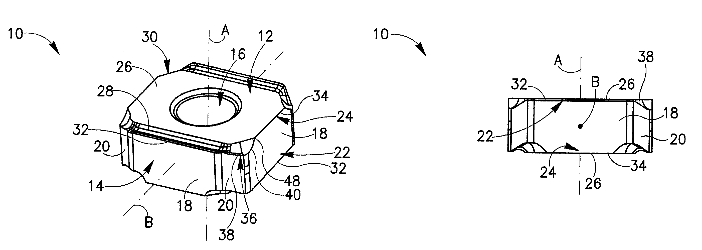
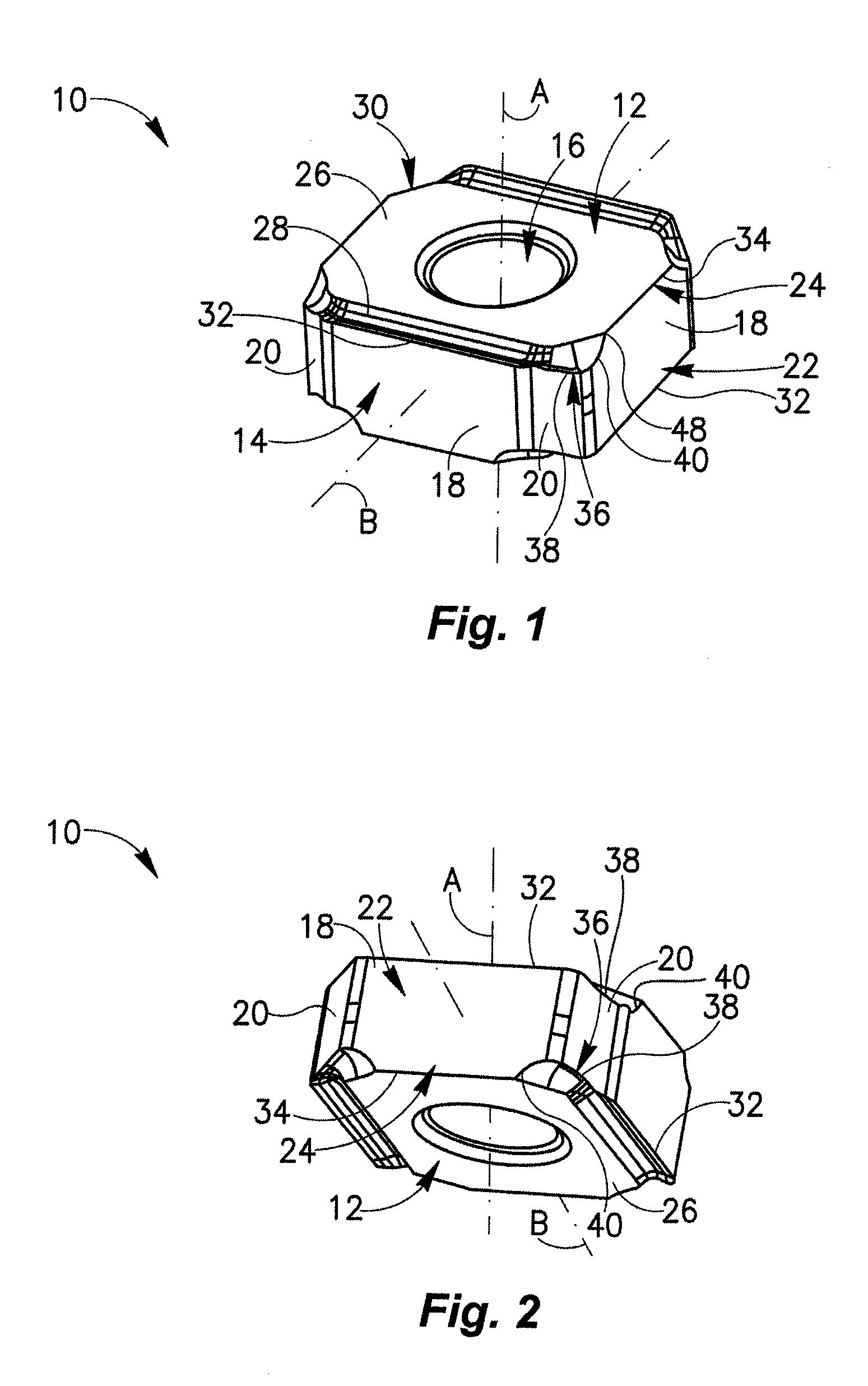
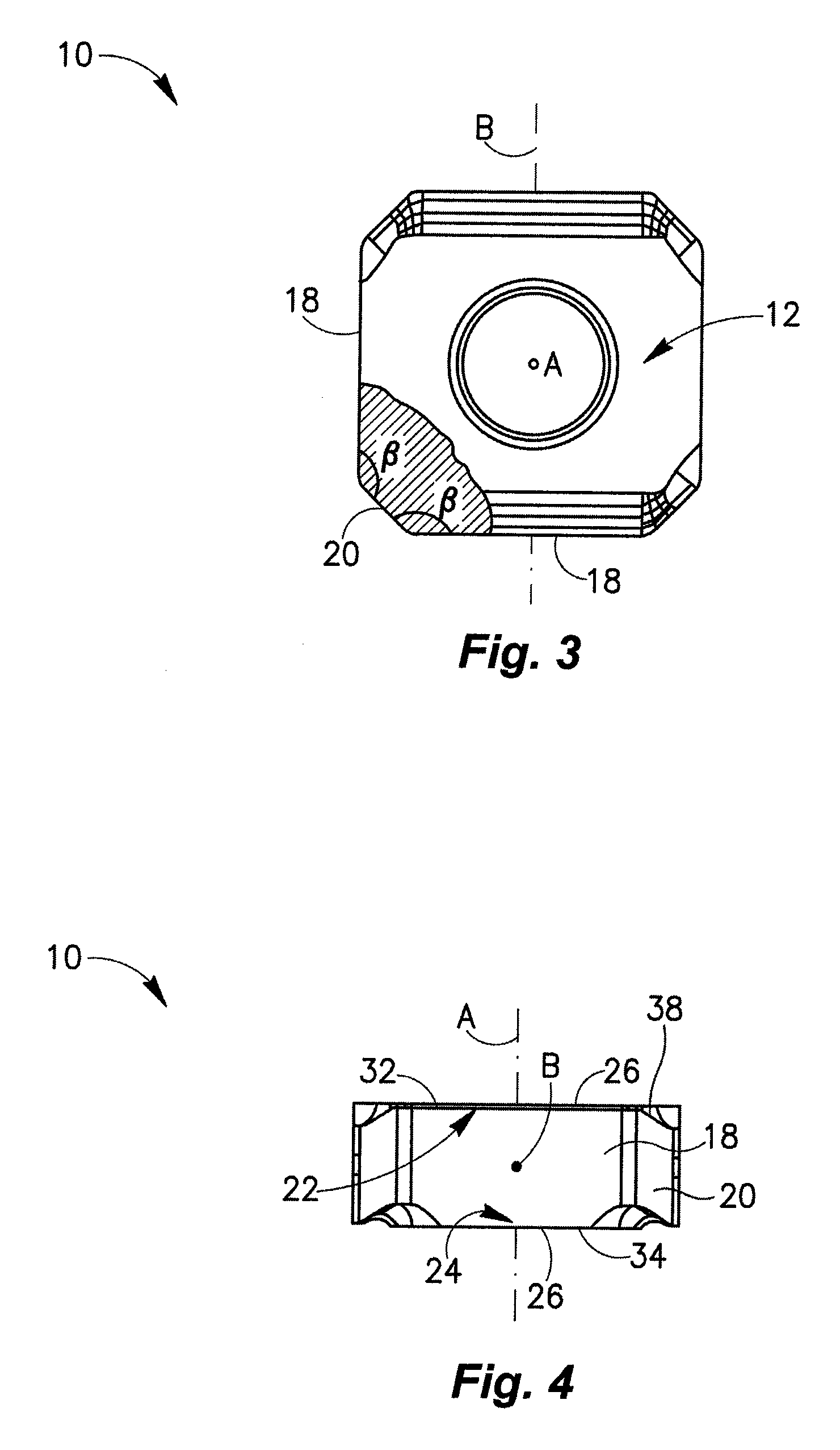
[0019]Attention is first drawn to FIGS. 1 to 3 showing an indexable cutting insert 10 which is typically manufactured by form pressing and sintering carbide powders. It should be noted that directional terms appearing throughout the specification and claims, e.g. “forward”, “rear”, etc., (and derivatives thereof) are for illustrative purposes only, and are not intended to limit the scope of the appended claims.

[0020]The cutting insert 10 has two identical opposing end surfaces 12 and a peripheral side surface 14 extending therebetween. The cutting insert 10 is of a negative type and therefore the peripheral side surface 14 is generally perpendicular to both end surfaces 12. A first axis A of the cutting insert 10 passes through the end surfaces 12 and a through bore 16 having a bore axis that coincides with the first axis A extends between the end surfaces 12.

[0021]The peripheral side surface 14 of the cutting insert 10 comprises four identical major faces 18 and four identical mino...


PUM

PropertyMeasurementUnit
Angleaaaaaaaaaa
Angleaaaaaaaaaa
Angleaaaaaaaaaa

Abstract

A cutting insert has two opposing end surfaces, a peripheral side surface extending therebetween and a peripheral edge formed at an intersection of each end surface with the peripheral side surface. The peripheral edge includes two minor edges and a cutting edge extending therebetween, a first section of each minor edge extending from the cutting edge generally towards the opposing end surface.

Description

FIELD OF THE INVENTION[0001]The present invention relates to a generally square cutting insert for use in metal cutting processes in general and for radial and axial turning in particular.BACKGROUND OF THE INVENTION[0002]Such cutting inserts have lateral faces which intersect at a radiused corner having a given radius and forming a corner angle therebetween. The larger the corner angle the smaller the radius may be without concern of the corner breaking. If the corner of such a cutting insert is truncated, the angle formed between each lateral face and a face of the truncated corner is enlarged and as a result a radius connecting each lateral face and the face of the truncated corner may be smaller. A cutting edge associated with each lateral face and ending at a small radius forms more uniform chips which reduces wear to the cutting insert.[0003]In order to increase the degree of indexability of the cutting insert, each lateral face should preferably form an identical angle with th...

Claims


Application Information

Patent Timeline
IPC IPC(8): B23B27/16
CPCB23B27/141B23B2200/0423B23B2200/0476B23B2200/201Y10T407/2274B23B2200/3609Y10T407/22Y10T407/23B23B2200/208B23B27/14B23B27/00
Inventor HECHTVASERMAN, ILANCOHEN, BENJAMYN
Owner ISCAR LTD
Features
  • Generate Ideas
  • Intellectual Property
  • Life Sciences
  • Materials
  • Tech Scout
  • Unparalleled Data Quality
  • Higher Quality Content
  • 60% Fewer Hallucinations
Learn More