Rocking key button assembly and electronic device using the same

a key button and assembly technology, applied in the direction of switches with three operating positions, contact mechanisms, electrical devices, etc., can solve the problems of difficult assembly, difficult assembly, and difficult assembly of key button assemblies, especially rocking assemblies

Inactive Publication Date: 2009-06-30
SHENZHEN FUTAIHONG PRECISION IND CO LTD +1
View PDF11 Cites 38 Cited by
  • Summary
  • Abstract
  • Description
  • Claims
  • Application Information

AI Technical Summary

Benefits of technology

[0008]FIG. 1 is an isometric and partial view of an electronic device using a rocking key button assembly according to the exemplary embodiment.

Problems solved by technology

Key button assemblies, especially rocking assemblies, can be difficult to assemble.
Assembly can be difficult due to the structure of the key button assembly and the relationship of the key button assembly with the housing.

Method used


Image

  • Rocking key button assembly and electronic device using the same
  • Rocking key button assembly and electronic device using the same
  • Rocking key button assembly and electronic device using the same

Examples


Embodiment Construction

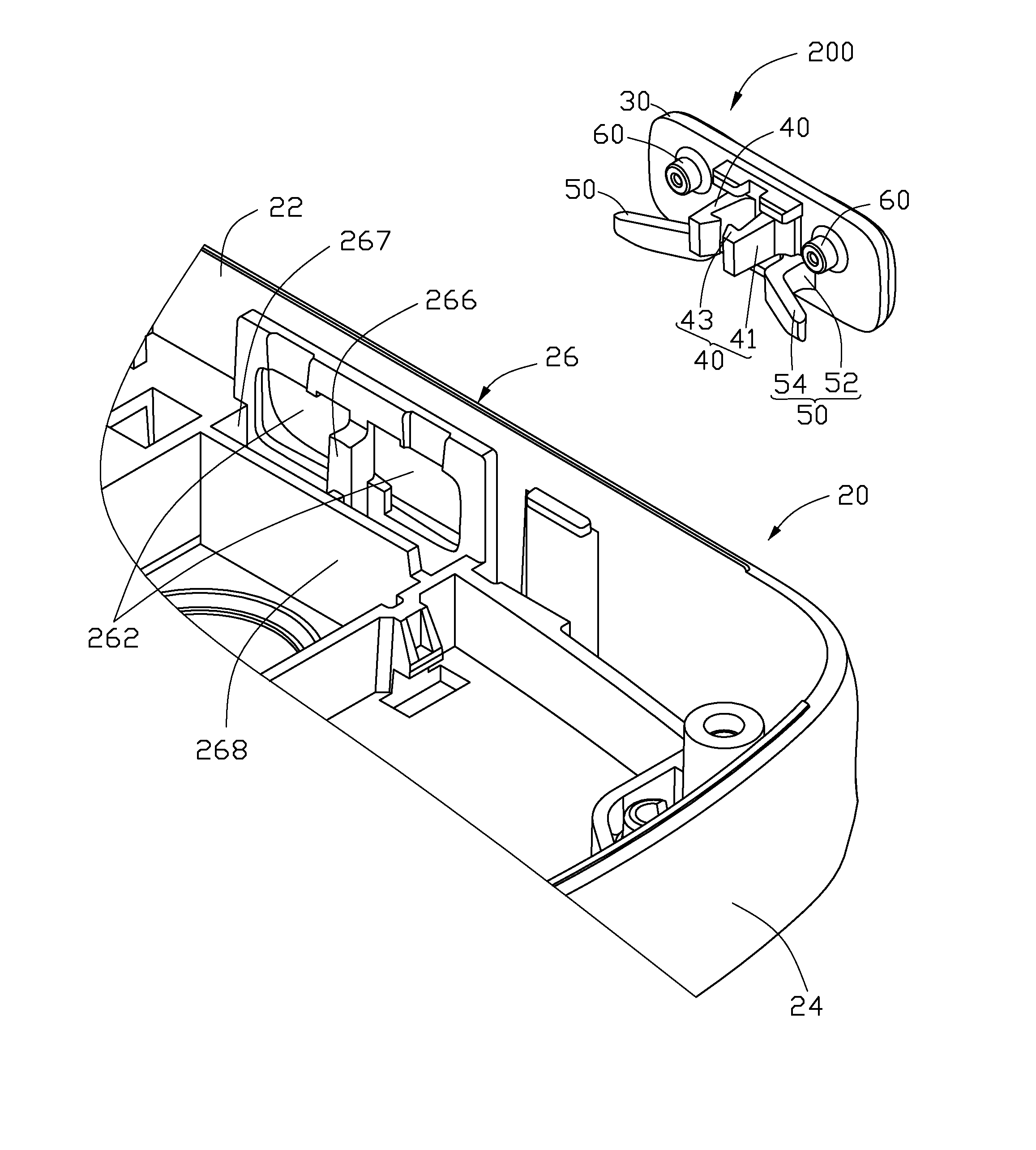
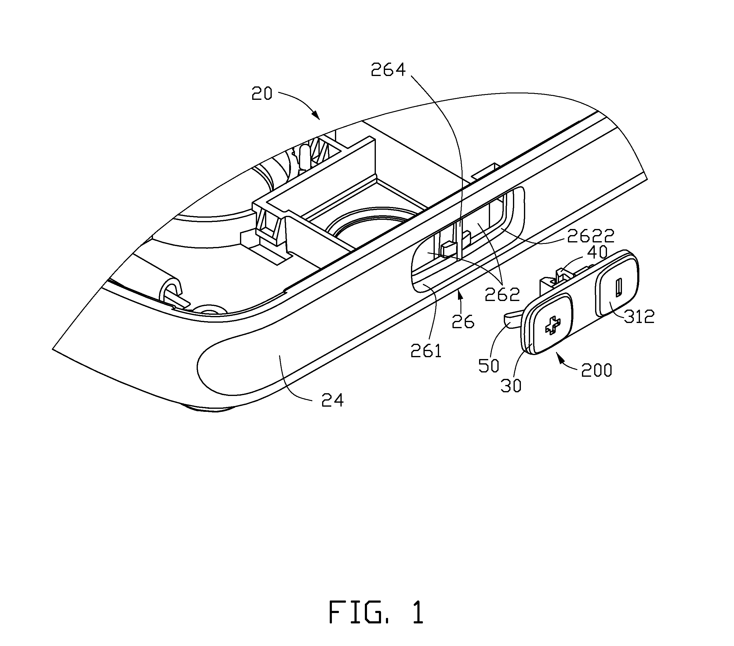
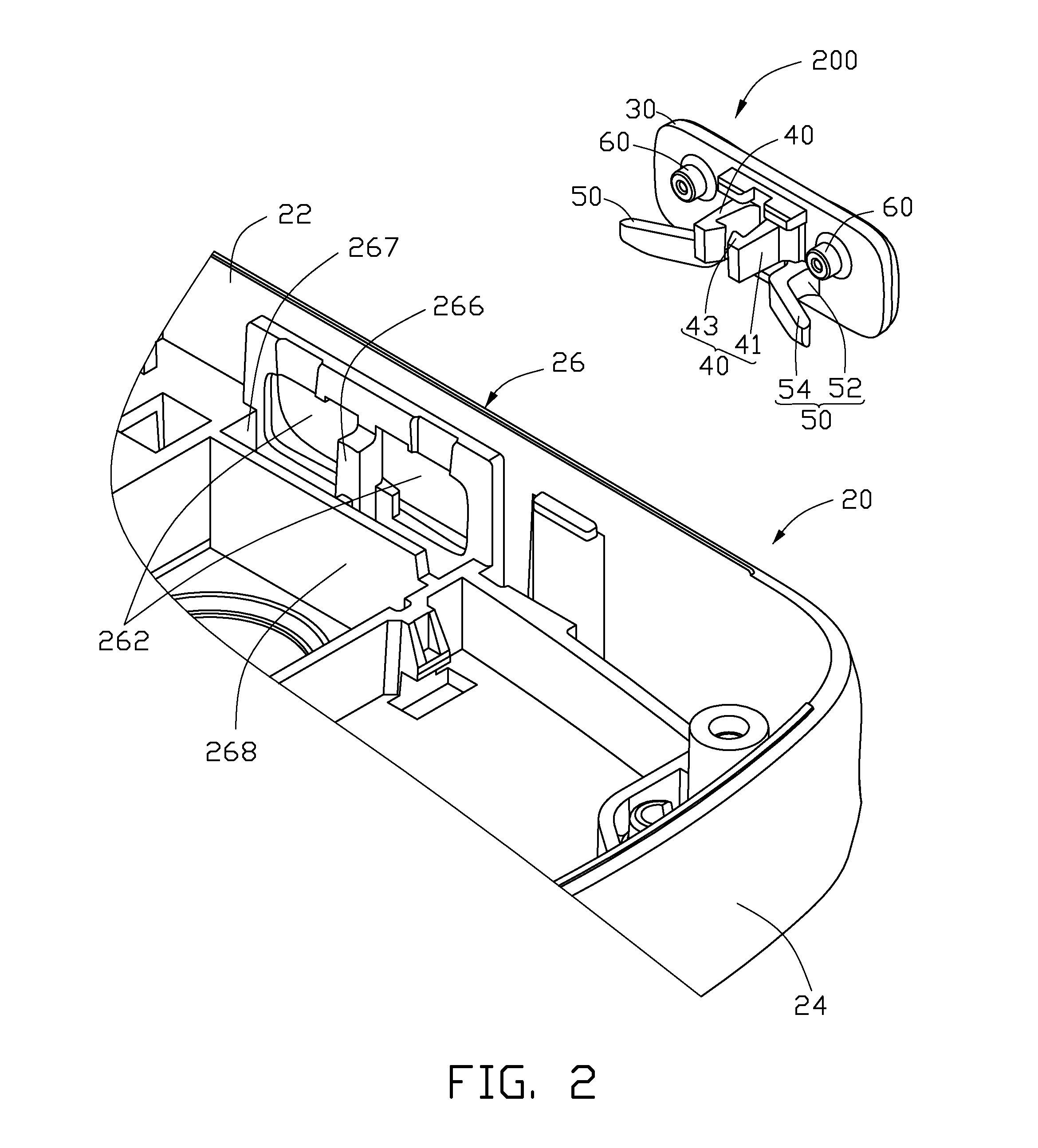
[0012]FIG. 1 shows an exemplary rocking key button assembly 200 used in an exemplary electronic device 20, such as cellular phone. The electronic device 20 includes a housing 24 and at least two circuit loops (not shown). One circuit loop can be for increasing volume. The other circuit loop can be for decreasing volume.

[0013]Housing 24 defines a mounting area 26 at which the rocking key button assembly 200 is mounted. The mounting area 26 defines a receiving groove 261 and two mounting holes 262, a shaft portion 264, a retaining portion 266, and a blocking board 268. The receiving groove 261 surrounds the two mounting holes 262, which are exposed to the inside of the housing 24. The two mounting holes 262 are separated from each other by the shaft portion 264. The shaft portion 264 faces the receiving groove 261. The retaining portion 266 faces the inside of the housing 24. Since the receiving groove 261 is larger than the mounting holes 262, a stepped wall 2622 surrounds the receiv...


PUM


Abstract

An electronic device (20) includes a housing (24) and a rocking key button assembly (200) rockingly assembled to the housing. The housing includes a shaft portion (264) and a blocking board (268). The key button assembly includes a key button (30) having two opposite key portions (312), two elastic retaining members (40), two elastic arms (50) and two triggers (60). The elastic retaining members are retained to the shaft portion. The elastic arms resist against the blocking board. The key portions can rock relative to each other and about the shaft portion, the corresponding one trigger swings relative to the other trigger and about the shaft portion. The corresponding elastic arm is compressed by the blocking board. The elastic retaining members, the elastic arms and the triggers are arranged at the same side of the key button opposite to the two keys.

Description

BACKGROUND[0001]1. Field of the Invention[0002]The invention relates to a rocking key button assembly used in an electronic device.[0003]2. Description of Related Art[0004]With rapid development of information technology, electronic devices, such as cellular phones, personal digital assistant (PDA), and so on, are become more and more popular. For general electronic devices, key buttons mechanisms may be arranged on two side surfaces of the electronic devices to provide command shortcuts. For example, key button mechanisms can be used for receiving a call or adjusting sound volume.[0005]Key button assemblies, especially rocking assemblies, can be difficult to assemble. Take a rocking key button assembly (including a key button and two holding members) for example. The holding members retain the key button within a housing of the electronic device. The key button has two shafts fixed to the housing. The key button rotates about the shafts and thus rocks relative to the housing. Assem...

Claims


Application Information

Patent Timeline
Patent Type & Authority Patents(United States)
IPC IPC(8): H01H23/00
CPCH01H23/30
Inventor LV, YUE-HUI
Owner SHENZHEN FUTAIHONG PRECISION IND CO LTD
Why Eureka
Try Eureka