Control of flexible riser curvature at the keel of a floating structure

a floating structure and curvature technology, applied in the field of offshore drilling and production platforms, can solve the problems of inability to optimally support the dynamic motion of the riser relative to the platform, fatigue and failure, etc., and achieve the effects of reducing the thickness of the pipe wall, increasing the weight per unit length, and increasing thickness

Active Publication Date: 2009-07-07
TECH FRANCE SA
View PDF7 Cites 3 Cited by
  • Summary
  • Abstract
  • Description
  • Claims
  • Application Information

AI Technical Summary

Benefits of technology

[0009]Broadly, the present invention is a bend limiting conduit or “stinger” for an SCR extending from the seafloor into the centerwell of a spar-type platform through the keel of the platform, wherein the bend limiting “stinger” extends from an upper end constrained within the keel of the platform to a lower end disposed below the keel, and defines a bore dimensioned to receive the SCR, characterized in that the stinger has progressively increasing flexibility or compliance from the upper end to the lower end. Advantageously, the stinger also increases in weight per unit length from the upper end to the lower end, with the stinger comprising a plurality of axial segments or sections joined end-to end, with the heavier segments or sections near the lower end, and the lighter segments or sections toward the upper end.
[0010]In a specific preferred embodiment, the stinger is formed from a series of steel pipe sections, or joints, of uniform inside diameter, joined axially (end-to-end), wherein each of the pipe sections or joints below the uppermost joint has an outside diameter that is slightly less than that of the joint immediately above it. This stepwise graduated reduction in the outside diameter with a constant inside diameter in successive joints is achieved by reducing the pipe wall thickness in each successive joint below the uppermost joint.
[0011]Also, in the preferred embodiment the weight per unit length is increased for each successive joint below the uppermost joint by applying a weighted “jacket” of increasing thickness on each successive joint below the uppermost joint. In a specific exemplary embodiment, the jacket comprises one or more layers of weighted metallic tape (e.g., lead tape) applied to the outside surface of each joint. Each successive joint below the uppermost joint is provided with a greater number of tape layers than the joint immediately above it. Alternatively, weighted collars or concrete cast directly onto the stinger joint may be installed on the pipe joints to create a desired weight distribution along the length of the stinger. The distribution of the weights makes the lower end of the bend limiting stinger heavier (per unit length) than the upper end, without significantly affecting the greater compliance (lower stiffness) of the lower end due to the lesser pipe wall thicknesses as compared to the upper end.
[0013]The bend-limiting stinger of the present invention is used with an SCR that extends from the seafloor up through the bore of the stinger and into the centerwell, where it assumes a vertical orientation as it extends up to the deck. Thus, upon entry into the lower end of the stinger, the SCR has a catenary curvature, and it exits from the upper end of the stinger in a vertical orientation. By constructing the stinger with increasing flexibility or compliance from its upper end to its lower end, and with similarly increasing weight per unit length, the SCR is made to transition gradually from its curved configuration to its vertical, linear configuration with little or no bending moment. The curvature of the SCR is controlled both by the distributed weight of the stinger, particularly along the more heavily-weighted lower portion, and by the graduated stiffness of the stinger, particularly along the less flexible upper portion. Furthermore, while the bend-limiting stinger of the present invention is of a smaller outside diameter than conventional bend limiters (so that it may pass through the riser guides, as discussed above), it can achieve better control of the curvature of the SCR than conventional bend limiters, due to its greater extent below the keel of the platform the aforementioned graduated transition in stiffness or flexibility and its above-described bottom-loaded weight distribution. Moreover, the bend-limiting stinger of the present invention is relatively compliant (not rigid), and thus it can move with the riser during dynamic motion of the hull, thereby reducing stresses imposed on the riser due to motion-induced changes in the riser curvature.

Problems solved by technology

In addition, the motion of the floating platform creates cyclical stresses on the riser that, over time, can result in fatigue and failure.
While such prior art bend limiters do result in some limitation of the bending moment in the riser, they are fixed in geometry and cannot optimally support the dynamic motion of the riser relative to the platform.
Furthermore, conventional bend limiters with fixed geometries typically cannot be run through the vertical riser guides in the centerwell of the platform, and thus the prior art bend limiters must be secured to or within the hull, independently of the available vertical riser guides.

Method used


Image

  • Control of flexible riser curvature at the keel of a floating structure
  • Control of flexible riser curvature at the keel of a floating structure
  • Control of flexible riser curvature at the keel of a floating structure

Examples


Embodiment Construction

[0018]As used herein, the terms “invention” and “present invention” are to be understood as encompassing the invention described herein in its various embodiments and aspects, as well as any equivalents that may suggest themselves to those skilled in the pertinent arts.

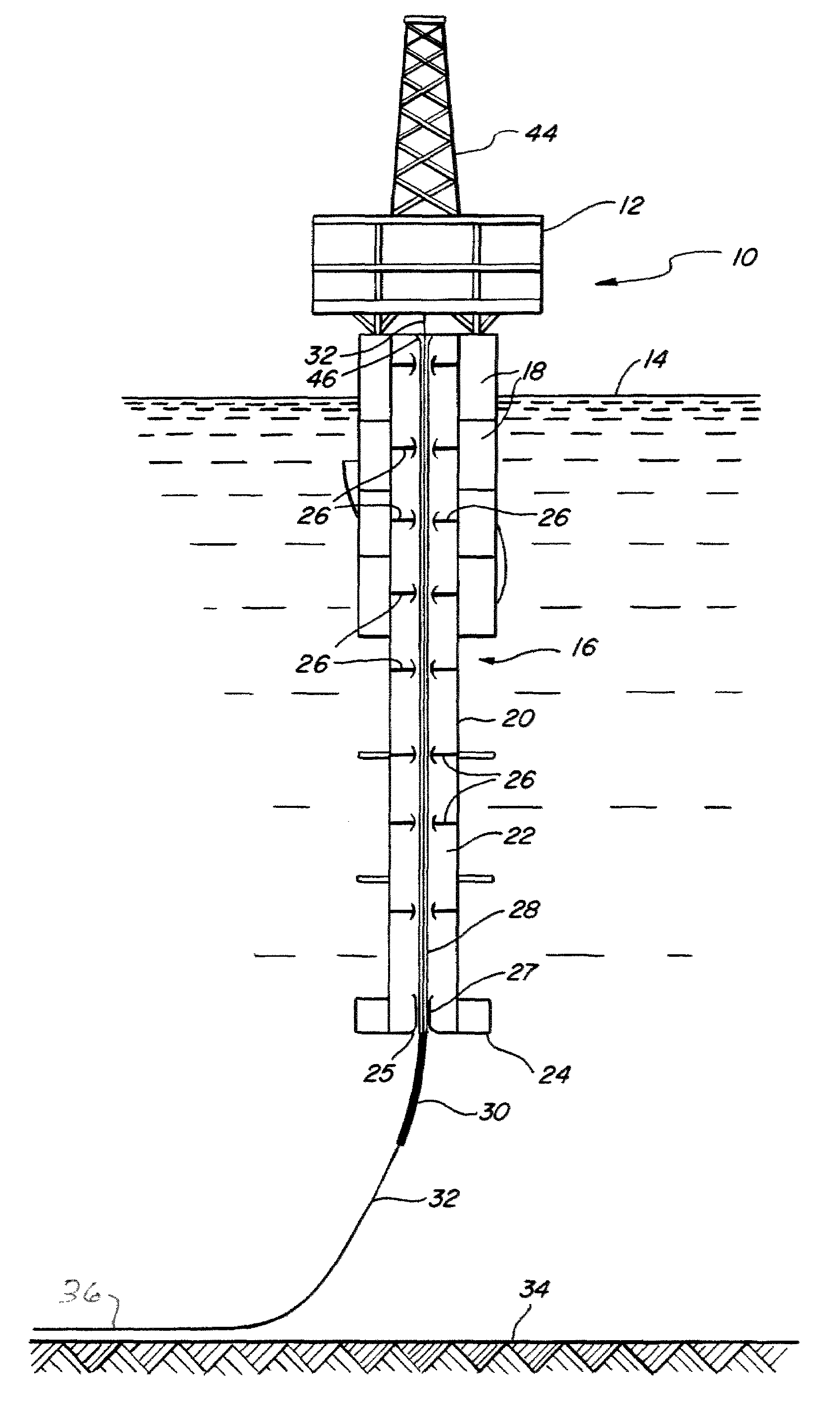
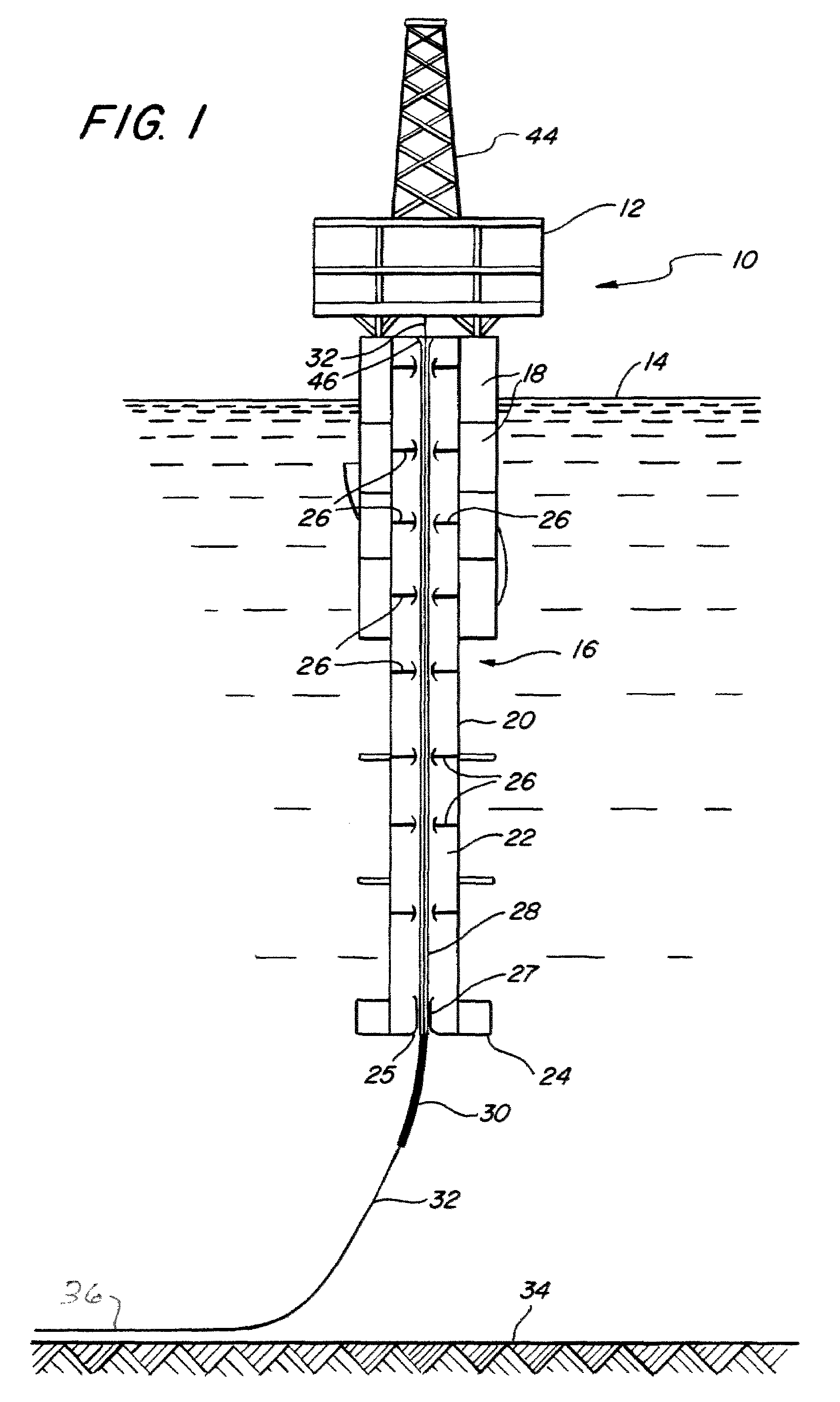
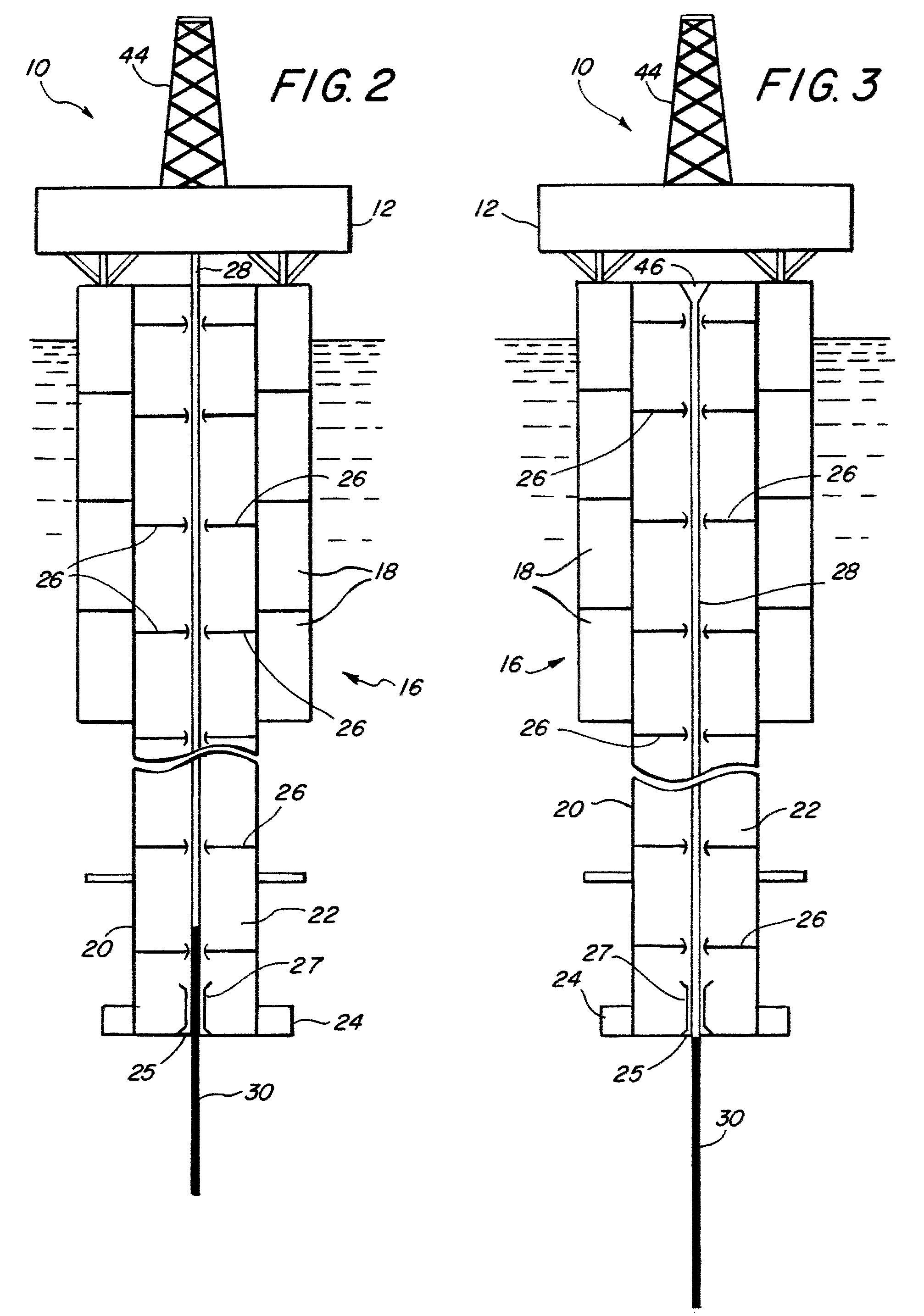
[0019]FIG. 1 shows a spar-type platform 10 of conventional design. The platform 10 comprises a deck structure 12 supported above the surface 14 of a body of water by a buoyant hull 16. The hull 16, in turn, comprises an array of buoyancy tanks 18, some of which are “hard” tanks (air-filled), and some of which are “soft” tanks (floodable with water for adjustable buoyancy). The tanks 18 are arranged around a central column 20 that defines a centerwell 22. The bottom end of the central hull column 20 terminates in a ballasted keel 24 having a bottom opening or slot 25 that communicates with the centerwell 22. A plurality of riser guides 26 are disposed at spaced intervals along the length of the centerwell 22, with a ke...


PUM


Abstract

A bend-limiting conduit controls the curvature of a catenary riser extending from the seafloor as it enters the centerwell of a spar-type offshore platform through the keel of the platform. The conduit has a bore dimensioned to receive the riser, and it extends from an upper end constrained within the keel to a lower end disposed below the keel. The conduit has increasing flexibility and weight per unit length from the upper end to the lower end, which results in a lateral load being applied to the riser as it passes through the conduit, thereby causing a gentle and gradual transition in the riser from a curved configuration at the lower end of the conduit, to a straight configuration as it emerges from the upper end of the conduit.

Description

CROSS-REFERENCE TO RELATED APPLICATION[0001]This applications claims the benefit, under 35 U.S.C. Section 119(e), of co-pending Provisional Application No. 60 / 822,561, filed Aug. 16, 2006, the disclosure of which is incorporated herein by reference in its entirety.FEDERALLY-SPONSORED RESEARCH OR DEVELOPMENT[0002]Not ApplicableBACKGROUND[0003]This disclosure relates to the field of offshore drilling and production platforms, particularly spar-type platforms. More specifically, it relates to platforms, such as spar-type platforms, that are used in conjunction with production and / or export / import risers, either in a vertical or catenary configuration. Still more specifically, it relates to a mechanism for coupling a riser configured in a catenary configuration to a platform through a set of riser guides in the platform designed for a vertical riser configuration in a way that controls the curvature of the catenary curve-configured riser at the bottom or keel of the platform so as to re...

Claims


Application Information

Patent Timeline
Patent Type & Authority Patents(United States)
IPC IPC(8): E21B17/01
CPCE21B17/017
Inventor O'SULLIVAN, JAMES
Owner TECH FRANCE SA
Why Eureka
Try Eureka