
Catheter safety needle

a safety needle and catheter technology, applied in the direction of catheters, infusion needles, guide needles, etc., can solve the problems of the tip posing a danger of the needle sticking to the medical personnel, and the health risk of the medical personnel administering the needl

Active Publication Date: 2009-07-07
MEDICAL COMPONENTS INC
View PDF25 Cites 80 Cited by
  • Summary
  • Abstract
  • Description
  • Claims
  • Application Information

AI Technical Summary

Benefits of technology

The present invention provides a catheter insertion needle assembly with a needle guard and a slider assembly. The slider assembly includes a slider and a needle with a needle body and a cannulating portion extending through the needle body. The needle extends distally of the slider and through the needle guard. The assembly also includes first and second locking members for securely holding the needle in place. The first locking tab is releasably engageable with the first locking member, while the second locking portion is lockably engageable with the second locking member. The first locking tab is releasable to allow the slider to slide between a distal position and a proximal position. The second locking portion engages the second locking member to prevent the slider from sliding distally. The assembly also includes first and second retention sections for releasably retaining the slider in a distal position and a proximal position, respectively. The technical effects of this invention include improved safety and ease of use during catheter insertion procedures.

Problems solved by technology

This sharp tip poses a danger of a needle stick to the medical personnel.
Addtionally, this tip is contaminated with the patient's blood, which leads to the danger of blood-borne pathogens, such as HIV or hepatitis, to contaminate the needle and pose a further health risk for the medical personnel administering the needle.

Method used


Image

  • Catheter safety needle
  • Catheter safety needle
  • Catheter safety needle

Examples


Embodiment Construction

[0014]In the drawings, like numerals indicate like elements throughout. Certain terminology is used herein for convenience only and is not to be taken as a limitation on the present invention. The words “proximal” and “distal” refer to directions away from and closer to, respectively, the insertion tip of the needle in the catheter insertion needle assembly according to the present invention. The terminology includes the words above specifically mentioned, derivatives thereof, and words of similar import. The following describes preferred embodiments of the invention. However, it should be understood based on this disclosure, that the invention is not limited by the preferred embodiments described herein.

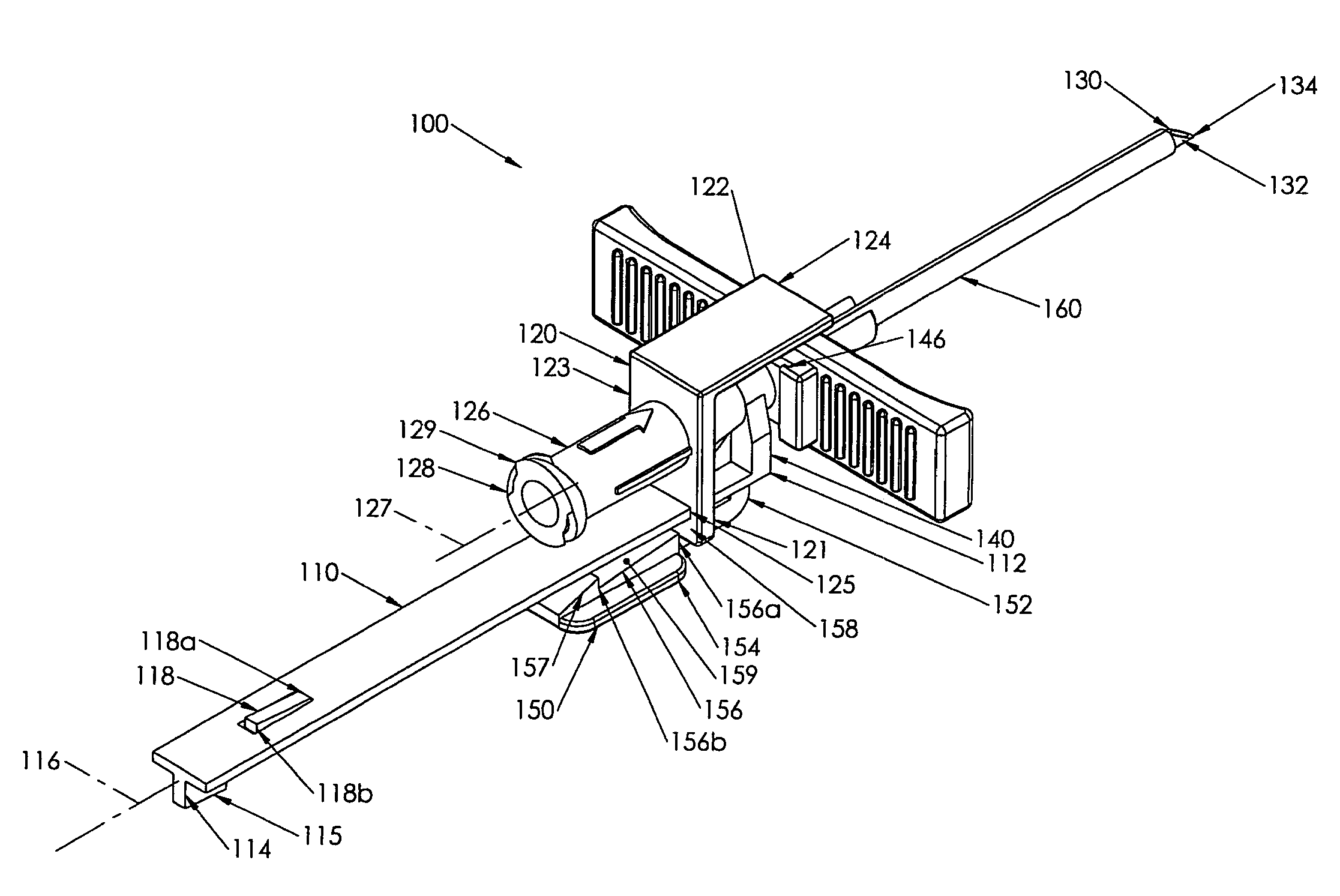
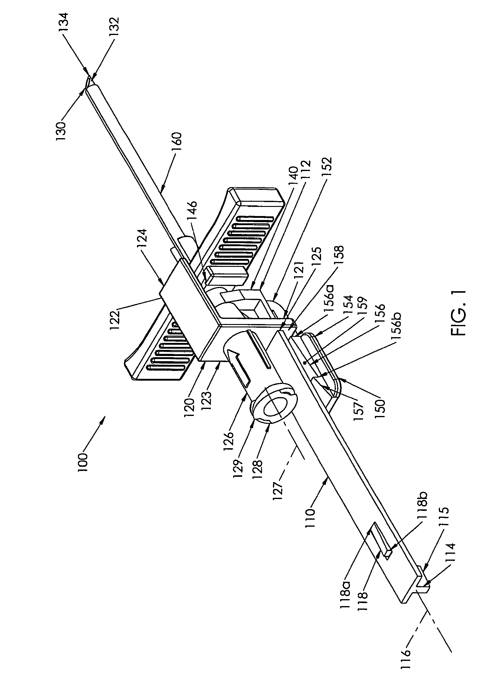
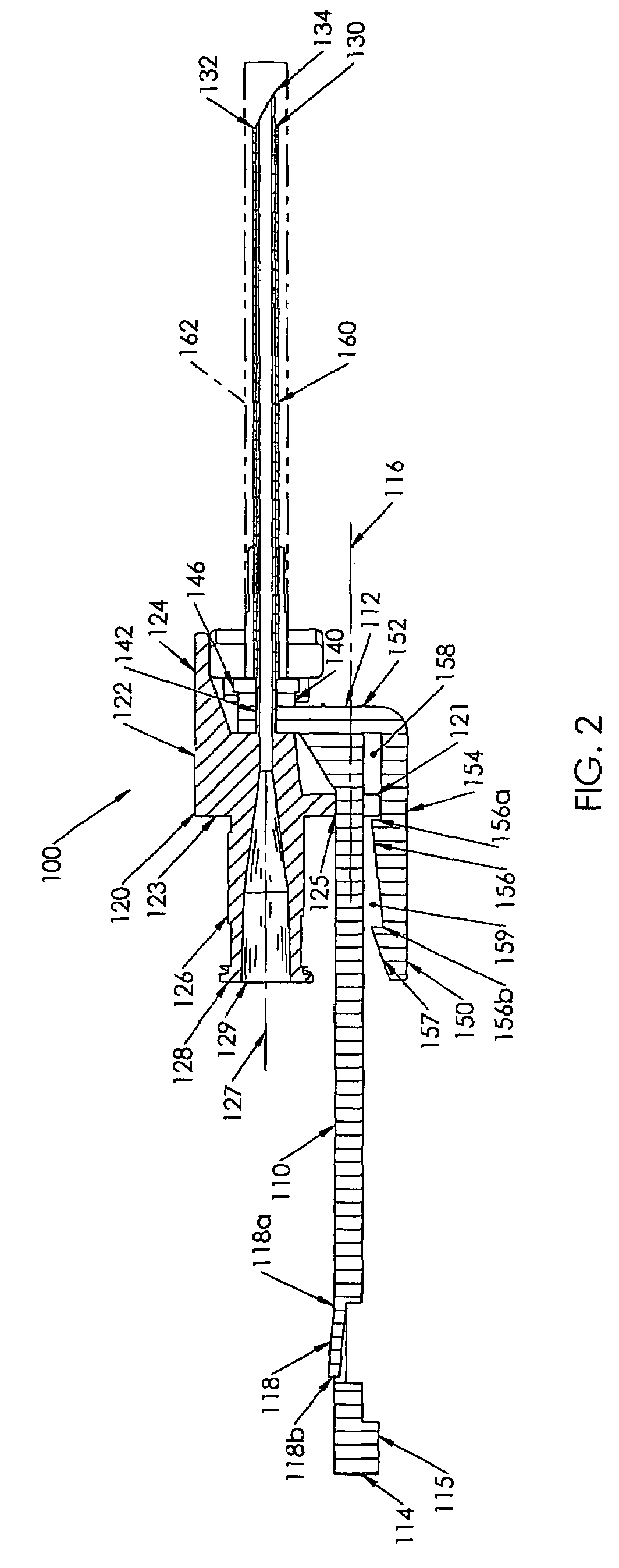
[0015]Referring to FIG. 1, a perspective view of a catheter insertion needle assembly 100 according to a first embodiment of the present invention is shown. The assembly 100 includes an elongated body 110, a slider assembly 120, a needle housing 126, a needle 130, and a needle guard...


PUM


Abstract

A catheter insertion needle assembly (100) including a generally elongated body (110), a slider assembly (120), and a needle housing (126) with a needle (130). The elongated body has a proximal end (114) and a distal end (112), a needle guard (140) disposed at the distal end of the body in a needle guard plane, a first or distal locking member (150), and a second or proximal locking member (118). The slider assembly (120) includes a slider (122) that is slidably disposed on the body (110) Needle (130) has a distal tip (134) and a cannulating portion (132) extending therethrough. A first locking tab (121) is releasably engageable with the first locking member (150) and a second locking portion is lockably engageable with the second locking member (118). The first locking tab (121) is releasable from the first locking member to allow the slider (122) to slide between a distal position relative to the body (110) wherein the tip (134) extends distally of the needle guard (140), and a proximal position relative to the body wherein the tip (134) is disposed within the needle guard plane. When the slider (122) is disposed at the proximal position, the second locking portion engages the second locking member (118) to preclude the slider (122) from sliding distally relative to the body (110).

Description

CROSS REFERENCE TO RELATED INVENTION[0001]The present application claims the benefit of U.S. Provisional Patent Application Ser. No. 60 / 548,427, filed on 26 Feb. 2004.FIELD OF THE INVENTION[0002]The present invention relates to a catheter insertion needle that is retractable into a safety position after use to prevent accidental sticks.BACKGROUND OF THE INVENTION[0003]The introduction of a device through tissue of a living body typically requires the use of a sharp instrument such as a scalpel or a needle to provide access into the tissue. For example, for the insertion of a catheter into a blood vessel a needle is used to access the vessel. The needle includes a hollow bore cannula that provides a conduit for an introducer device, such as a guide wire, to be inserted through the cannula and into the blood vessel. After insertion of the guide wire, the needle is withdrawn proximally along the guide wire and discarded. The catheter is then inserted into the vessel over the guide wire...

Claims


Application Information

Patent Timeline
Patent Type & Authority Patents(United States)
IPC IPC(8): A61M5/178A61M5/32A61M25/06
CPCA61M25/0631A61M5/3269
Inventor VOORHEES, JR., EARL W.STEPHENS, JOHNCHESNIN, KENNETH J.
Owner MEDICAL COMPONENTS INC
Learn More