
Method of detecting and compensating for faults in an MRI process

a fault and process technology, applied in the field of mri scanning equipment and processes, can solve problems such as negative effects, negative effects on scan data and images, and mri image data could suffer from artifacts

Active Publication Date: 2009-07-07
FONAR
View PDF5 Cites 15 Cited by
  • Summary
  • Abstract
  • Description
  • Claims
  • Application Information

AI Technical Summary

Benefits of technology

The invention allows for receiving and analysis of MRI scan data generated during a scan. This may be done either through manual interpretation from a human operator or via automated analysis with a computer-controlled MRI scanning device. The removal of unnecessary data can occur afterwards or during the scan itself depending upon the desired outcome.

Problems solved by technology

The technical problem addressed in this patent relates to identifying and correcting errors in magnetic resonance imaging procedures caused by hardware/software issues, environmental factors, etc., to produce high-quality images without significant loss of image quality.

Method used


Image

  • Method of detecting and compensating for faults in an MRI process
  • Method of detecting and compensating for faults in an MRI process
  • Method of detecting and compensating for faults in an MRI process

Examples


Embodiment Construction

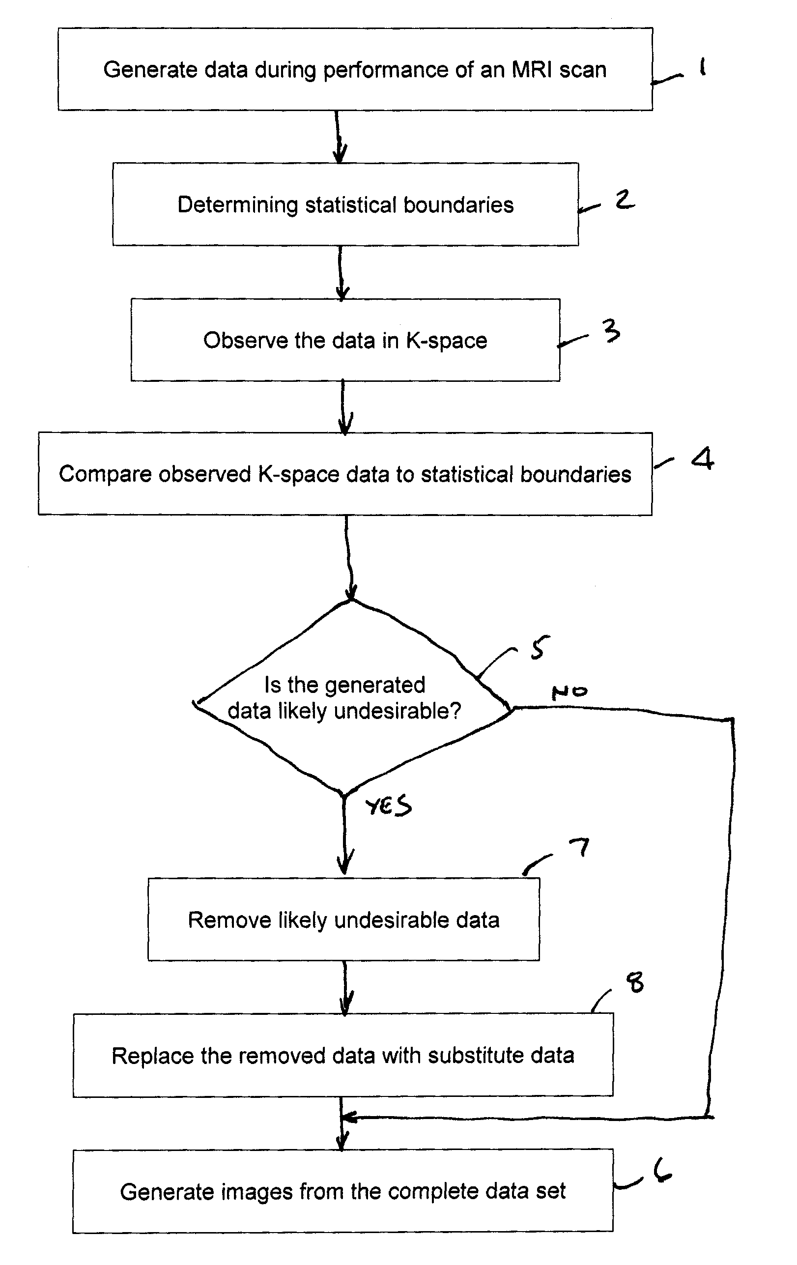
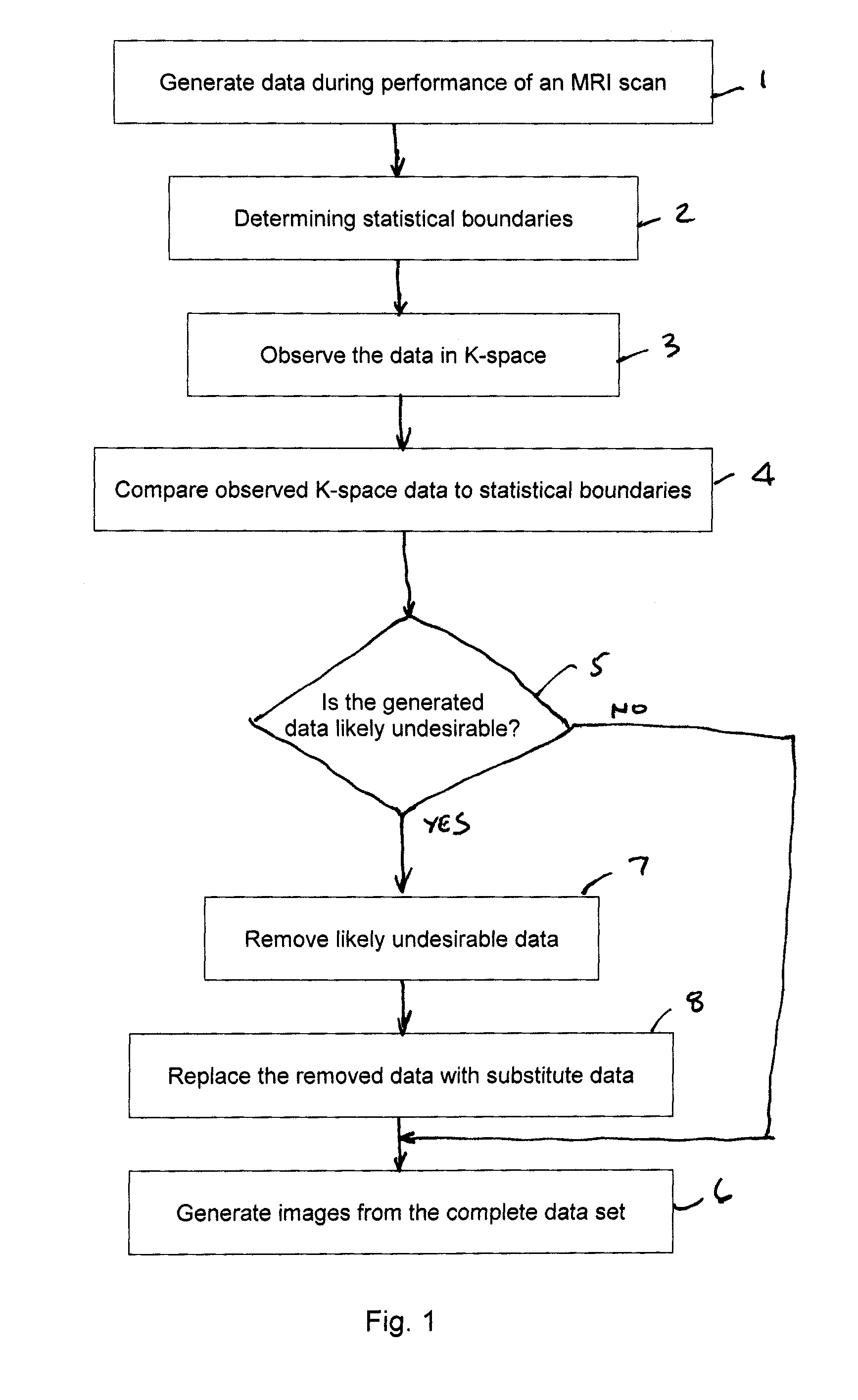
[0023]Valid NMR data have some known statistical boundaries. Therefore, one can analyze the K-space data acquired during a scan and can make a general determination as to whether some of the acquired data are not valid, that is, is likely to produce an image that does not have sufficient diagnostic value according to certain criteria. That is, data that is found to be outside of a predetermined statistical boundary can be deemed invalid and removed from ‘K’ space and replaced.

[0024]There are three modes anticipated for compensating for data that are determined to be undesirable. According to the first mode, image data is acquired. After the scan is complete, a validity analysis is performed, preferably by a skilled operator, and data that are determined to be invalid are removed and replaced.

[0025]According to the second mode of operation, a computer process controls the scan procedure and acquires image data. After the scan is complete, a validity analysis is performed by a compute...


PUM


Abstract

According to a method of detecting and compensating for MRI scan errors, MRI scan data are received. At least one statistical boundaries is determined for the generated data. The data are observed in K-space. The observed K-space data are compared to the determined statistical boundary. Data that are likely undesirable, based on the comparison, are removed. The removed data are replaced with substitute data to modify the data set. Images are generated from the modified data set.

Description


Claims


Application Information

Patent Timeline
Owner FONAR
Learn More