Wide bandwidth microwave balun

Active Publication Date: 2009-07-07
TAMIRAS PER PTE LTD LLC
View PDF3 Cites 18 Cited by
  • Summary
  • Abstract
  • Description
  • Claims
  • Application Information

AI Technical Summary

Benefits of technology

[0023]In operation, the desired amplified signals at the balanced outputs of the amplifier are equal in amplitude are 180 degrees out of phase. In contrast, unwanted or spurious signals, such as second order intermodulation distortion signals, are approximately in phase at the balanced output ports of the amplifier. Since the

Problems solved by technology

However, at microwave frequencies it becomes increasingly difficult to fabricate this class of balun and other techniques become necessary.
Miniaturization of the balun to a size and planar form compatible with monolithic microwave integrated circuit, MMIC, fabrication further complicates the design and implementation of the balun.
While it is known to cancel second-order distortion in the front ends of amplifiers and to do so in the microwave region of the electromagnetic spectrum, the problem is that in an amplifier, to cancel second harmonics the balun has to be operating from the lowest input frequency to twice the highest output frequency.
If one is operating near a radio station and one happens to be listening to a weaker station further away, the presence of the large signal from the nearby radio station can create spurious tones due to the above-mentioned non-linearities in an amplifier.
This makes it virtually impossible or very diff

Method used


Image

  • Wide bandwidth microwave balun
  • Wide bandwidth microwave balun
  • Wide bandwidth microwave balun

Examples


Example

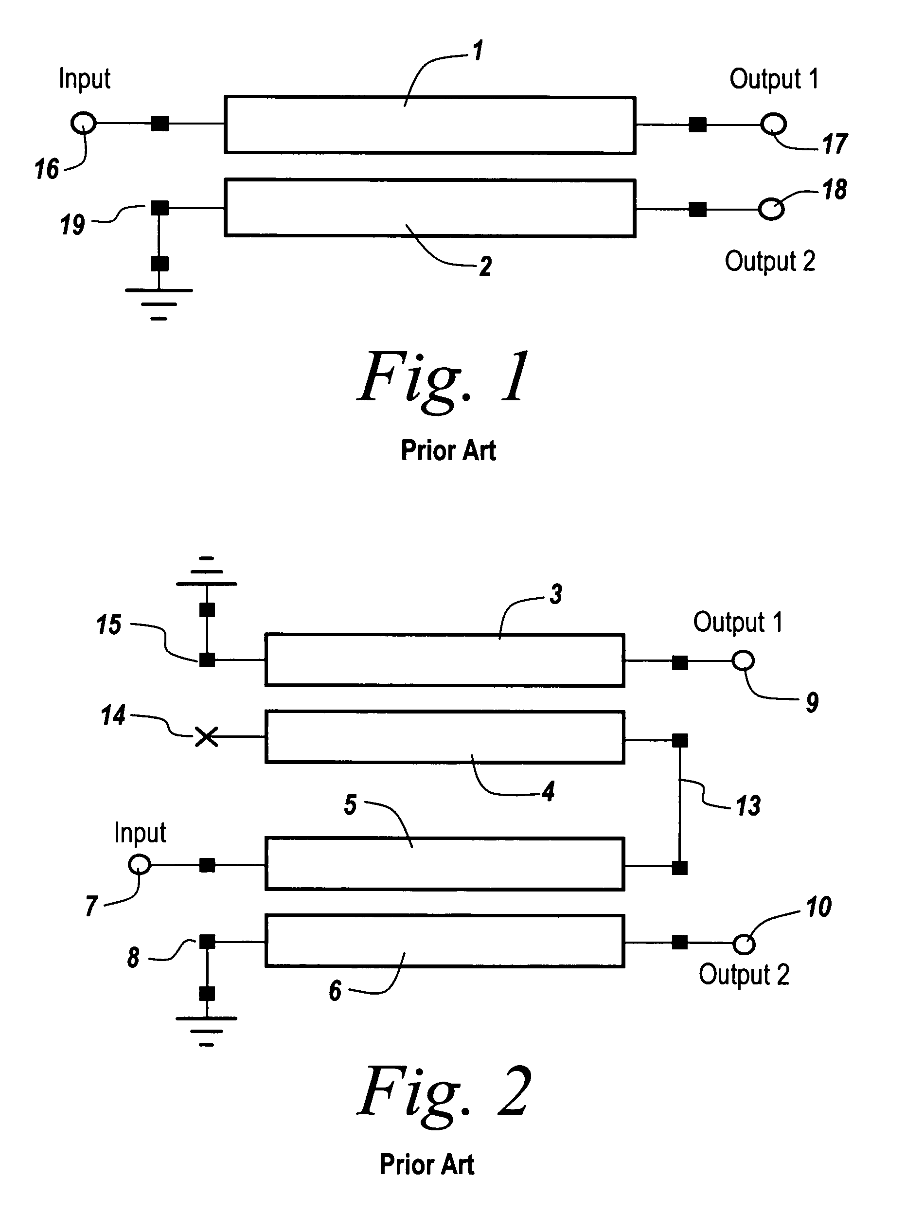
[0038]Referring now to FIG. 1, the design of the subject bal-plex balun begins with the design of the individual upper and lower band baluns. It is noted that the frequency bands must overlap enough to allow a smooth transition and a smooth frequency response, but not so much as to lose the frequency response at the highest and lowest frequencies.

[0039]Referring now to FIG. 1, one type of simple conventional balun uses coupled lines 1 and 2. The bandwidth for this circuit is approximately one octave centered on the quarter-wave frequency of the coupled lines. Note that as will be described later, the input to the balun is unbalanced across terminals 16 and 19, with terminal 19 grounded, whereas the balanced output is available across terminals 17 and 18.

[0040]Referring to FIG. 2, a compensated balun is shown whose architecture is used for the low frequency band balun of the subject invention. This compensated balun is illustrated as having coupled lines 3 and 4 and coupled lines 5 a...


PUM


Abstract

A wide bandwidth microwave balun utilizes frequency band splitting and two conventional baluns operating in a high frequency band and a low frequency band, which when combined offer a full bandwidth output, thus to offer wide bandwidth impedance matching and second-harmonic rejection.

Description

RELATED APPLICATIONS[0001]This Application claims rights under 35 USC § 119(e) from U.S. Application Ser. No. 60 / 780,640 filed Mar. 9, 2006, the contents of which are incorporated herein by reference.STATEMENT OF GOVERNMENT INTEREST[0002]This invention was made with United States Government support under a classified contract. The United States Government has certain rights in this invention.FIELD OF THE INVENTION[0003]This invention relates to microwave and RF circuits and more particularly to baluns used in such circuits.BACKGROUND OF THE INVENTION[0004]An essential component in many microwave and RF circuits is the balanced to unbalanced transformer or balun. Balun applications include balanced mixers, multipliers, and amplifiers for cancellation of even order intermodulation products, power amplifiers for push-pull power combining, and for the connection of naturally balanced antenna structures to unbalanced microwave components.[0005]Low frequency baluns leverage ferrite and ai...

Claims


Application Information

Patent Timeline
IPC IPC(8): H03H7/42H03H7/48
CPCH01P1/213H03H7/463H01P5/10
Inventor MEHARRY, DAVID E.
Owner TAMIRAS PER PTE LTD LLC
Why Eureka
Try Eureka