FRONT END MODULE FOR 5.2 GHz Wi-Fi ACOUSTIC WAVE RESONATOR RF FILTER CIRCUIT

a filter circuit and front end module technology, applied in diversity/multi-antenna systems, gated amplifiers, low noise amplifiers, etc., can solve the problems of complex driving of rf in smartphones, limitations of conventional rf technology, and challenges in using and transferring single crystal piezoelectric thin films. , to achieve the effect of minimizing the layout area in applications, saving power consumption, and simple and cost-effectiv

Active Publication Date: 2019-01-31
AKOUSTIS INC
View PDF5 Cites 9 Cited by
  • Summary
  • Abstract
  • Description
  • Claims
  • Application Information

AI Technical Summary

Benefits of technology

[0008]One or more benefits are achieved over pre-existing techniques using the invention. In particular, the present device can be manufactured in a relatively simple and cost effective manner while using conventional materials and / or methods according to one of ordinary skill in the art. In an example, the present FEM design provides a compact form factor and integrated matching minimizes layout area in applications. The PA can be optimized for a 5V supply voltage that conserves power consumption while maintaining a high linear output power and throughput. Also, an integrated BAW filter reduces the overall size for Wi-Fi radio applications and allows coexistence between the 5.2 GHz radio band and adjacent 2.4 GHz and 5.6 GHz bands in a tri-band router configuration. The present device can be configured with an ultra-small form factor RF resonator filter with high rejection, high power rating, and low insertion loss. Such filters or resonators can be implemented in an RF filter device, an RF filter system, or the like. Depending upon the embodiment, one or more of these benefits may be achieved.

Problems solved by technology

Coexistence of new and legacy standards and thirst for higher data rate requirements is driving RF complexity in smartphones.
Unfortunately, limitations exist with conventional RF technology that is problematic, and may lead to drawbacks in the future.
Even so, there are challenges to using and transferring single crystal piezoelectric thin films in the manufacture of BAWR and BAW filters.

Method used


Image

  • FRONT END MODULE FOR 5.2 GHz Wi-Fi ACOUSTIC WAVE RESONATOR RF FILTER CIRCUIT
  • FRONT END MODULE FOR 5.2 GHz Wi-Fi ACOUSTIC WAVE RESONATOR RF FILTER CIRCUIT
  • FRONT END MODULE FOR 5.2 GHz Wi-Fi ACOUSTIC WAVE RESONATOR RF FILTER CIRCUIT

Examples


Embodiment Construction

[0042]According to the present invention, techniques generally related to electronic devices are provided. More particularly, the present invention provides techniques related to a method of manufacture and structure for bulk acoustic wave resonator devices, single crystal resonator devices, single crystal filter and resonator devices, and the like. Merely by way of example, the invention has been applied to a single crystal resonator device for a communication device, mobile device, computing device, among others.

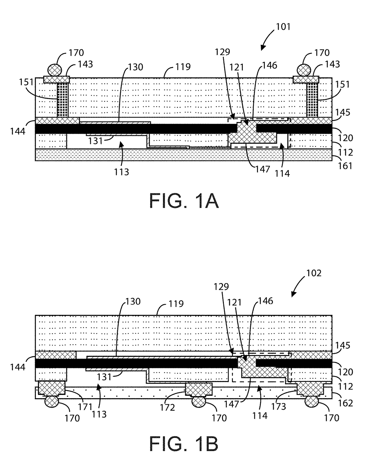
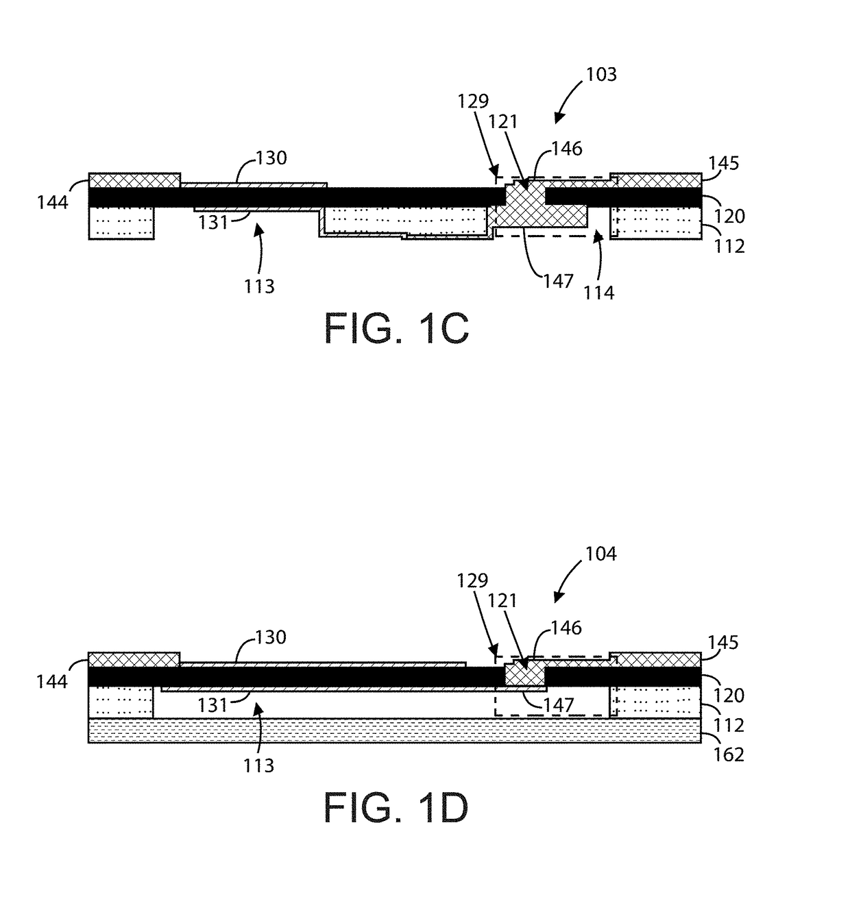
[0043]FIG. 1A is a simplified diagram illustrating an acoustic resonator device 101 having topside interconnections according to an example of the present invention. As shown, device 101 includes a thinned seed substrate 112 with an overlying single crystal piezoelectric layer 120, which has a micro-via 129. The micro-via 129 can include a topside micro-trench 121, a topside metal plug 146, a backside trench 114, and a backside metal plug 147. Although device 101 is depict...


PUM


Abstract

A front end module (FEM) for a 5.2 GHz Wi-Fi acoustic wave resonator RF filter circuit. The device can include a power amplifier (PA), a 5.2 GHz resonator, and a diversity switch. The device can further include a low noise amplifier (LNA). The PA is electrically coupled to an input node and can be configured to a DC power detector or an RF power detector. The resonator can be configured between the PA and the diversity switch, or between the diversity switch and an antenna. The LNA may be configured to the diversity switch or be electrically isolated from the switch. Another 5.2 GHZ resonator may be configured between the diversity switch and the LNA. In a specific example, this device integrates a 5.2 GHz PA, a 5.2 GHZ bulk acoustic wave (BAW) RF filter, a single pole two throw (SP2T) switch, and a bypassable LNA into a single device.

Description

CROSS-REFERENCES TO RELATED APPLICATIONS[0001]The present application claims priority to and is a continuation-in-part application of U.S. patent application Ser. No. 16 / 019,267, (Attorney Docket No. 969RO0007US3) titled “5.2 GHz Wi-Fi ACOUSTIC WAVE RESONATOR RF FILTER CIRCUIT,” filed Jun. 26, 2018, which is a continuation-in-part application of U.S. patent application Ser. No. 15 / 784,919, (Attorney Docket No. 969RO0007US2) titled “PIEZOELECTRIC ACOUSTIC RESONATOR MANUFACTURED WITH PIEZOELECTRIC THIN FILM TRANSFER PROCESS,” filed Oct. 16, 2017, which is a continuation-in-part of U.S. application Ser. No. 15 / 068,510 filed Mar. 11, 2016. The present application incorporates by reference, for all purposes, the following concurrently filed patent applications, all commonly owned: U.S. patent application Ser. No. 14 / 298,057, (Attorney Docket No. A969RO-000100US) titled “RESONANCE CIRCUIT WITH A SINGLE CRYSTAL CAPACITOR DIELECTRIC MATERIAL”, filed Jun. 6, 2014 (now U.S. Pat. No. 9,673,384...

Claims


Application Information

Patent Timeline
Patent Type & Authority Applications(United States)
IPC IPC(8): H04B7/08H04B1/00H03F1/26H03H3/02
CPCH04B7/0814H04B1/006H03F1/26H03H3/02H03F2200/294H03H9/02118H03H2003/023H03H9/173H03H9/175H03H2003/025H03F3/195H03F3/72H03F2200/451H03F2203/7239
Inventor SHEALY, JEFFREY B.HOULDEN, ROHAN W.GIBB, SHAWN R.AICHELE, DAVID M.
Owner AKOUSTIS INC
Why Eureka
Try Eureka